Bulb changer attachment system

a technology of attachment system and light bulb, which is applied in the field of vacuum tools, can solve the problems of many consumers experiencing difficulty in changing light bulb, failure of light bulb after repeated use, and virtually inaccessible to consumers

Inactive Publication Date: 2014-07-22
WORKMAN ERNEST
View PDF9 Cites 5 Cited by
  • Summary
  • Abstract
  • Description
  • Claims
  • Application Information

AI Technical Summary

Benefits of technology

[0012]In view of the foregoing disadvantages inherent in the known light bulb changing tools art, the present invention provides a novel bulb changer attachment system. The general purpose of the present invention, which will be described subsequently in greater detail is to provide a vacuum tool used to couple to and change light bulbs located in ceiling light fixtures quickly and easily.
[0014]The light bulb (being changed) is couplably-received by the conical suction light bulb receiver such that an apex of the light bulb is suction-contacted by the proximal end of the conical suction light bulb receiver and an outer periphery is suction-contacted via the distal end of the conical suction light bulb receiver. The distal end of the conical suction light bulb receiver comprises a diameter greater than the proximal end of the conical suction light bulb, making the shape conical. A distance between the distal end and the proximal end of the conical suction light bulb is variable since the conical suction light bulb receiver comprises the soft, flexible rubber, enabling varying sizes of the light bulb to be changed. Further, the conical suction light bulb receiver is removeably-coupleable to the light bulb enabling a user to remotely access the light bulb from a hard-to-reach surface and remove the light bulb via a negative pressure placed on the light bulb.

Problems solved by technology

These lights fail after repeated use and need to be changed.
Unfortunately, many consumers experience difficulty changing light bulbs in hard to reach areas such as in ceiling light fixtures.
These bulbs can be very high up, and may therefore be virtually inaccessible to consumers without the use of stools or ladders.
Further, standing on stools, ladders, and other objects may prove dangerous, and may put users at risk of falling and incurring injuries.
This can be particularly risky and difficult for elderly or less agile individuals.
Additionally, light bulbs may break when being grasped to be changed creating risk of injury for such individuals.

Method used


Image

  • Bulb changer attachment system
  • Bulb changer attachment system
  • Bulb changer attachment system

Examples


Embodiment Construction

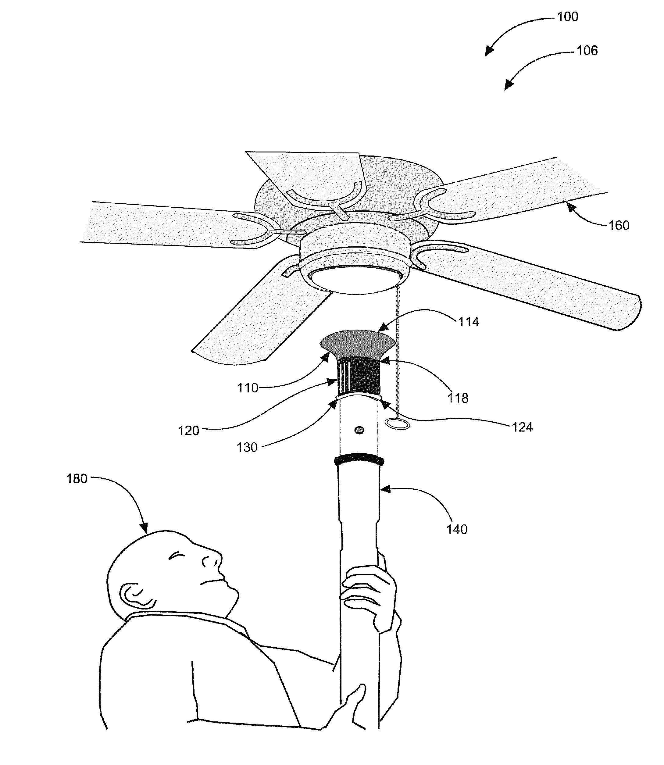
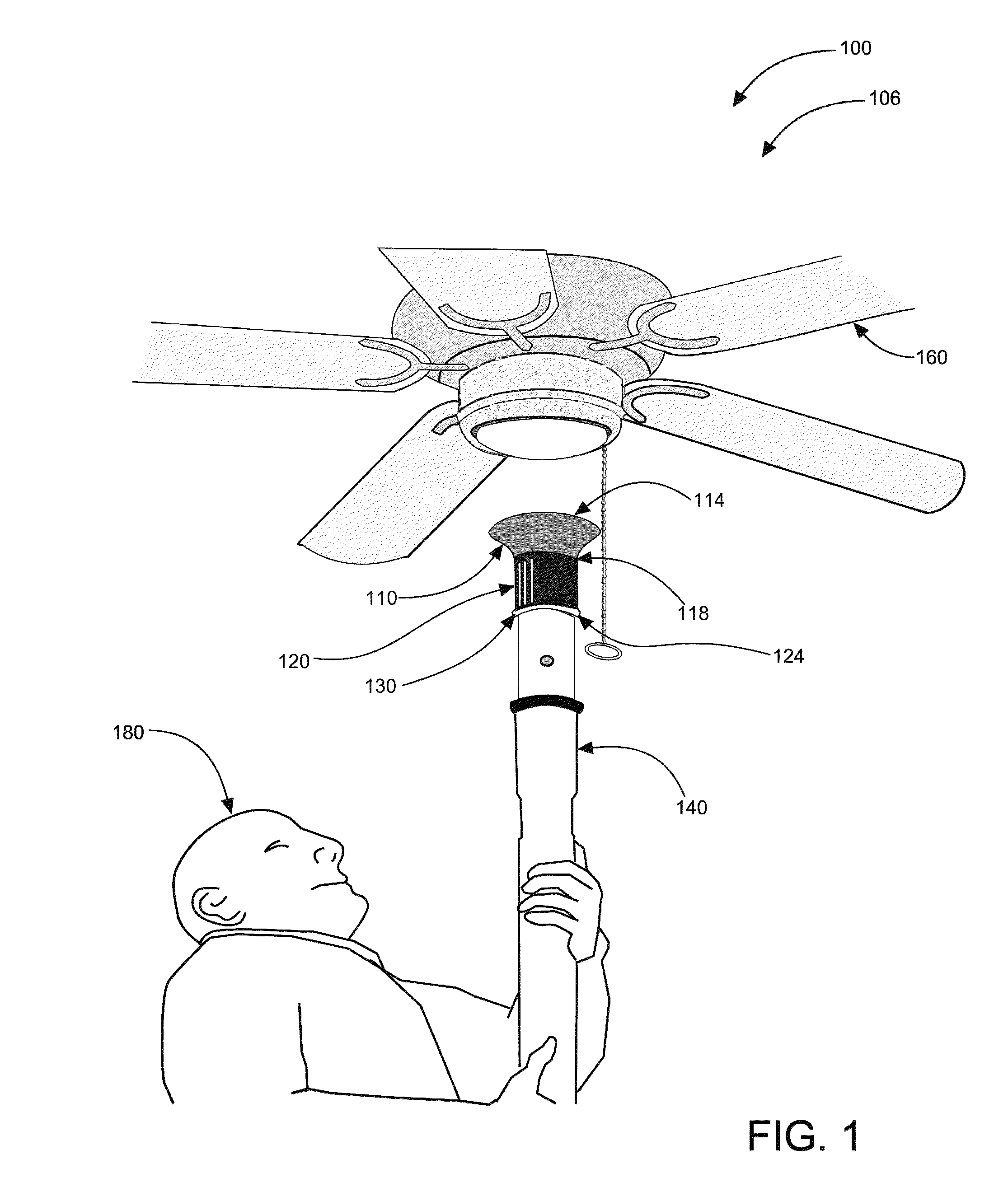
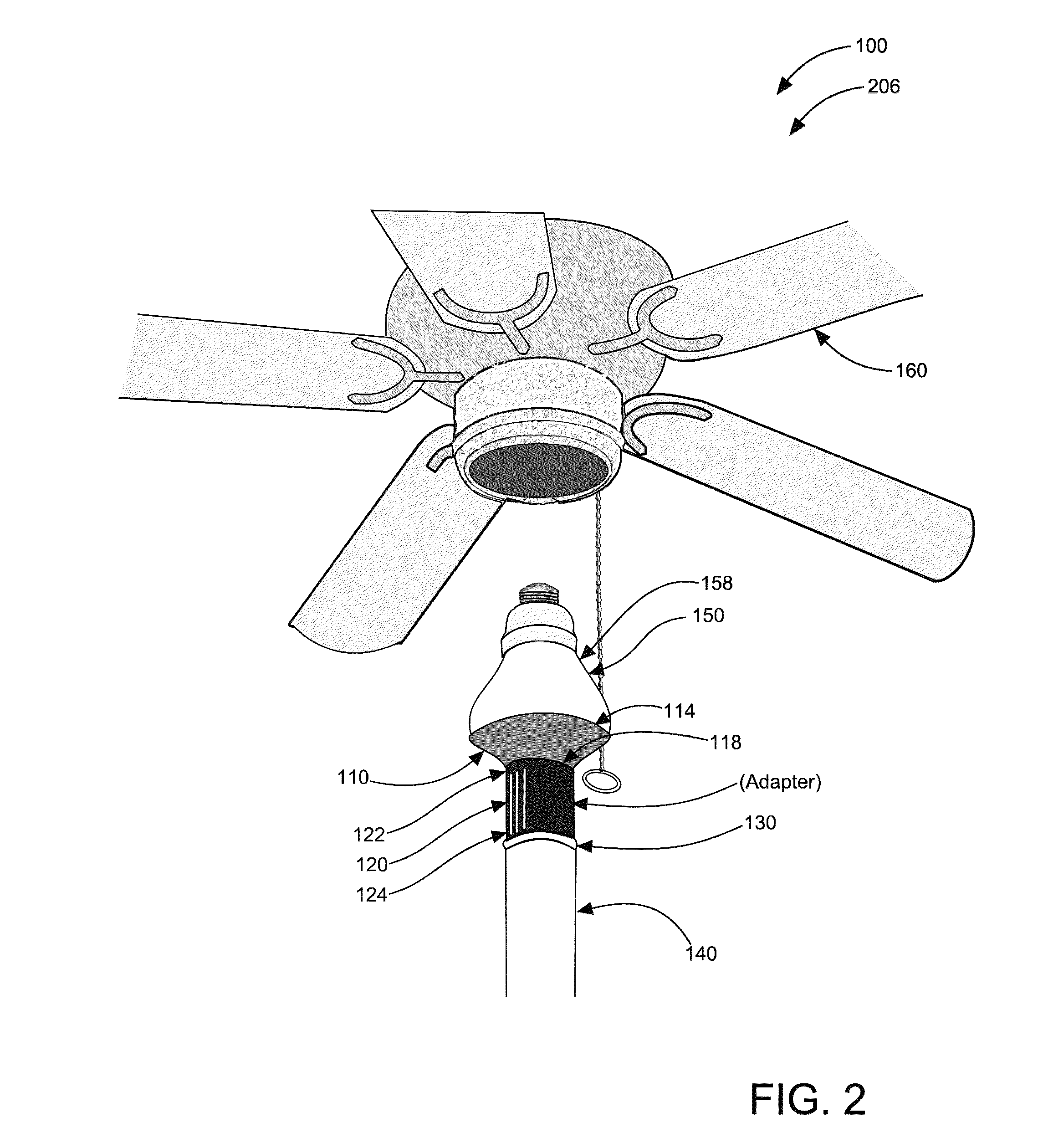
[0028]As discussed above, embodiments of the present invention relate to a vacuum tool used to change a light bulb and more particularly to a bulb changer attachment system that quickly and easily changes light bulbs located in ceiling light fixtures and to avoid the above-mentioned problems.

[0029]Referring now to FIGS. 1-3 showing perspective views of bulb changer attachment system 100 in ‘in-use’ condition 106 and ‘in-use’ condition 206 according to embodiments of the present invention. Bulb changer attachment system 100 preferably comprises conical suction light bulb receiver 110, base 120, adapter 130, and vacuum hose attachment 140. Conical suction light bulb receiver 110 is removeably-coupleable to light bulb 150 enabling user 180 to remotely access light bulb 150 from a hard-to-reach location and remove light bulb 150 via a negative pressure placed on light bulb 150. The hard-to-reach location may include but is not limited to a ceiling, or near a top portion of a wall, such ...


PUM


Abstract

A bulb changer attachment system comprising: a conical suction light bulb receiver having a distal end and a proximal end; a base having a top portion and a bottom portion; an adapter; and a vacuum hose attachment providing vacuum communication with at least one vacuum. The conical suction light bulb receiver is connected to the top portion of the base while the bottom portion of the base is connectable to the vacuum hose attachment via the adapter. A light bulb is received by the conical suction light bulb receiver such that an apex of the light bulb is suction-contacted by the proximal end of the conical suction light bulb receiver and an outer periphery is suction-contacted via the distal end of the conical suction light bulb receiver. The conical suction light bulb receiver is removeably-coupleable to the light bulb enabling a user to remotely access the light bulb for changing.

Description

CROSS-REFERENCE TO RELATED APPLICATION[0001]The present application is related to and claims priority from prior provisional application Ser. No. 61 / 409,443, filed Nov. 2, 2010 which application is incorporated herein by reference.COPYRIGHT NOTICE[0002]A portion of the disclosure of this patent document contains material which is subject to copyright protection. The copyright owner has no objection to the facsimile reproduction by anyone of the patent document or the patent disclosure, as it appears in the Patent and Trademark Office patent file or records, but otherwise reserves all copyright rights whatsoever. 37 CFR 1.71(d).[0003]The following includes information that may be useful in understanding the present invention(s). It is not an admission that any of the information provided herein is prior art, or material, to the presently described or claimed inventions, or that any publication or document that is specifically or implicitly referenced is prior art.BACKGROUND OF THE IN...

Claims


Application Information

Patent Timeline
Patent Type & Authority Patents(United States)
IPC IPC(8): H01K3/32
CPCH01J9/003H01K3/32
Inventor WORKMAN, ERNEST
Owner WORKMAN ERNEST
Why Eureka
Try Eureka