Eureka AIR delivers breakthrough ideas for toughest innovation challenges, trusted by R&D personnel around the world.

Plug-type connector

a plug-type connector and connector technology, applied in the direction of securing/insulating coupling contact members, coupling device connections, electrical devices, etc., can solve the problems of inability to shift the contact element by external forces, the contact element or the connection to the contact carrier element can be destroyed, and the contacting in the plug-type connector can be interrupted in an undesired manner

Active Publication Date: 2014-07-29
PHOENIX CONTACT GMBH & CO KG
View PDF32 Cites 0 Cited by
  • Summary
  • Abstract
  • Description
  • Claims
  • Application Information

AI Technical Summary

Benefits of technology

[0006]More than one contact element is preferably provided in the contact carrier element, whereby the individual conductors or wires of the cable are arranged in a contact element in the contact carrier element. The conductors or the cable are / is preferably designed as especially rigid conductors or a cable. According to one aspect of the disclosure, the contact element in the contact carrier element can have two different states. In the first state, the contact element is permanently fixed in the contact carrier element, so that it cannot be moved inside the contact carrier element. In this state, for example, the introduction of the individual conductor into the contact element preferably takes place so that during the connection of the wire to the plug-type connector no shifting of the contact element is possible, in order to be able to produce the most reliable connection possible or the most reliable coupling. In the first, fixed state the contact element is preferably arranged in a middle position along the longitudinal axis of the contact carrier element. As used herein, the term “middle position” mean that room for the movement for the contact element is free behind and in front of the contact element in the longitudinal direction of the contact carrier element so that the contact element can be shifted in the axial direction into a position to the right and to the left of the middle position. In the second state the contact element is not stationarily fixed in the contact carrier element but can be moved inside the contact carrier element. In order to transfer the contact element from the first state into the second state a force is necessary that must be applied onto the contact element that is greater than the holding force that fixes the contact element stationarily in the contact carrier element. Such a force can be applied, for example, in that the cable arranged in the plug-type connector is bent, as a result of which a shifting movement of the individual conductors of the cable is produced. If such a force acts on the contact element, which force is greater than the holding force of the fixing, the fixing is released so that the contact element is no longer arranged fixed in the contact carrier element but rather is movably mounted in the contact carrier element. In this state the contact element can be moved inside the contact carrier element in accordance with the force acting on the contact element. As a result, the longitudinal differences between the individual conductors that are produced during the bending of the cable can be compensated, which can prevent the contacting of the conductors in the plug-type connector from being interrupted and / or damaged. This makes it possible to ensure a particularly reliable contacting that can even be ensured if the cable already arranged in the plug-type connector must be bent by the application of high forces.
[0010]The fixing of the contact element is preferably formed by at least one catch means arranged on the contact element. This catch means arranged on the contact element can hook, for example, in an opening formed on the contact carrier element in order to fix the contact element in the first state, whereby the catch means can disengage out of the opening by exerting a force on the catch means that is greater than the holding force of the fixing in the opening in order to be able to allow a shifting of the contact element relative to the contact carrier element. The catch means is preferably provided on the conductor connection clamp, whereby two catch means are preferably provided on the conductor connection clamp that are formed on opposing side surfaces of the conductor connection clamp. The catch means can be constructed, for example, as a type of projection or convexity from the side surface of the conductor connection clamp. Furthermore, it is also possible to construct the catch means in the manner of a pin or a stud. In addition to the exerting of the holding force, the catch means can additionally prevent the contact element from being able to slide out from the contact carrier element in an undesired manner.

Problems solved by technology

The contact elements are customarily permanently connected to the contact carrier element so that a shifting of the contact element by forces acting externally is not possible.
If the force acting from the outside becomes too great, the contact element or the connection to the contact carrier element can be destroyed.
As a result, the contacting in the plug-type connector can be interrupted in an undesired manner.

Method used


Image

  • Plug-type connector
  • Plug-type connector
  • Plug-type connector

Examples


Embodiment Construction

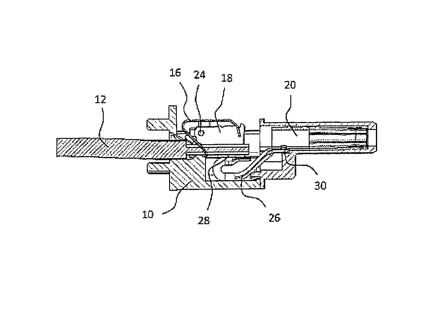
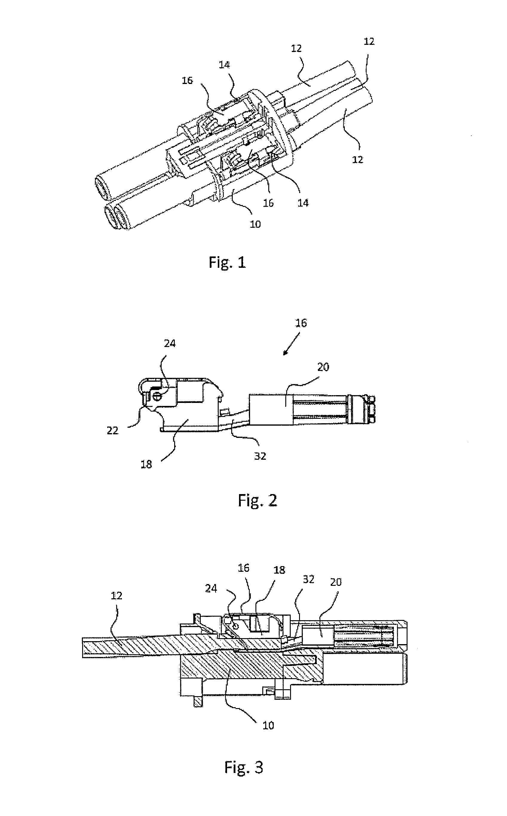
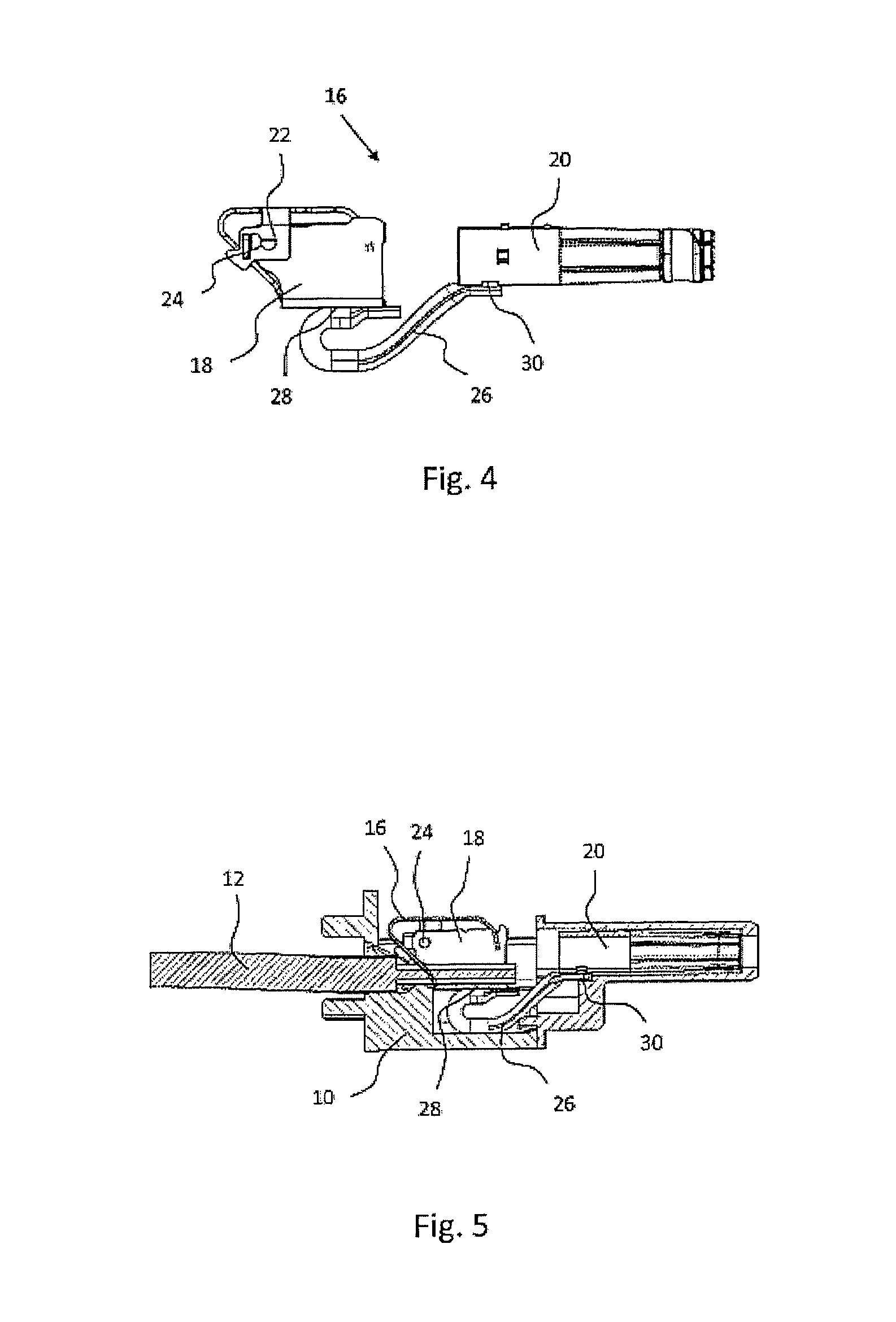
[0017]For the purposes of promoting an understanding of the principles of the invention, reference will now be made to the embodiments illustrated in the drawings and specific language will be used to describe the same. It will nevertheless be understood that no limitation of the scope of the invention is thereby intended, such alterations and further modifications in the illustrated device, and such further applications of the principles of the invention as illustrated therein being contemplated as would normally occur to one skilled in the art to which the invention relates. FIG. 1 shows a schematic view of a plug-type connector in accordance with the disclosure with a contact carrier element 10 produced from a non-conductive material, for example, a plastic material, inside of which element 10 several conductors 12 of a cable can be received for the contacting. In order to receive each individual conductor 12 a contact element 16 is arranged for each conductor 12 inside the conta...


PUM


Abstract

The subject matter of the invention is a plug-type connector, comprising a contact carrier element (10), wherein a contact element (16) for receiving a conductor (12) of a cable is arranged in the contact carrier element (10), wherein the contact element (16) is fixed in the contact carrier element (10), wherein, in the event of a force being exerted on the contact element (16) which is greater than the holding force of the fixing, the fixing can be released and the contact element (16) becomes movably mounted in the contact carrier element (10).

Description

CROSS-REFERENCE TO RELATED APPLICATIONS[0001]This application is a continuation of International Application No. PCT / EP2011 / 053753, filed Mar. 11, 2011, which claims the benefit of German Application No. 10 2010 011 371.9 filed Mar. 12, 2010, the entire disclosures of which are hereby incorporated by reference.FIELD OF THE INVENTION[0002]The invention relates to a plug-type connector with a contact carrier element inside of which one or more contact elements for receiving one or more conductors or wires of a cable can be arranged for producing a contacting (e.g., an electrical connection).BACKGROUND OF THE INVENTION[0003]Such plug-type connectors customarily comprise a contact carrier element manufactured from a non-conductive material, wherein the contact carrier element can receive, for example, multiple (e.g., three or five or more) contact elements for producing an electrically conductive connection to a cable or to the individual conductors or wires of a cable. The contact elem...

Claims


Application Information

Patent Timeline
Patent Type & Authority Patents(United States)
IPC IPC(8): H01R13/41
CPCH01R4/4818H01R13/111H01R13/40H01R13/6315H01R4/48185
Inventor NEHM, DETLEFFUHRER, THOMASSCHULTE, HANS-HILMAR
Owner PHOENIX CONTACT GMBH & CO KG
Why Eureka
Eureka Blog
Learn More