Pool caddy

a technology for automatic cleaning and caddy, which is applied in the direction of mechanical equipment, other domestic objects, machine supports, etc., can solve the problem that the device does not allow a user to pick up an automatic cleaning

Inactive Publication Date: 2014-08-12
BRASELL JAMES M
View PDF8 Cites 1 Cited by
  • Summary
  • Abstract
  • Description
  • Claims
  • Application Information

AI Technical Summary

Problems solved by technology

Devices do not allow a user to pick up an automatic pool cleaner and quickly stow it to a side of the pool, while allowing the automatic pool cleaner to remain on.

Method used


Image

  • Pool caddy
  • Pool caddy
  • Pool caddy

Examples


Embodiment Construction

[0016]The following detailed description is of the best currently contemplated modes of carrying out exemplary embodiments of the invention. The description is not to be taken in a limiting sense, but is made merely for the purpose of illustrating the general principles of the invention, since the scope of the invention is best defined by the appended claims.

[0017]Various inventive features are described below that can each be used independently of one another or in combination with other features.

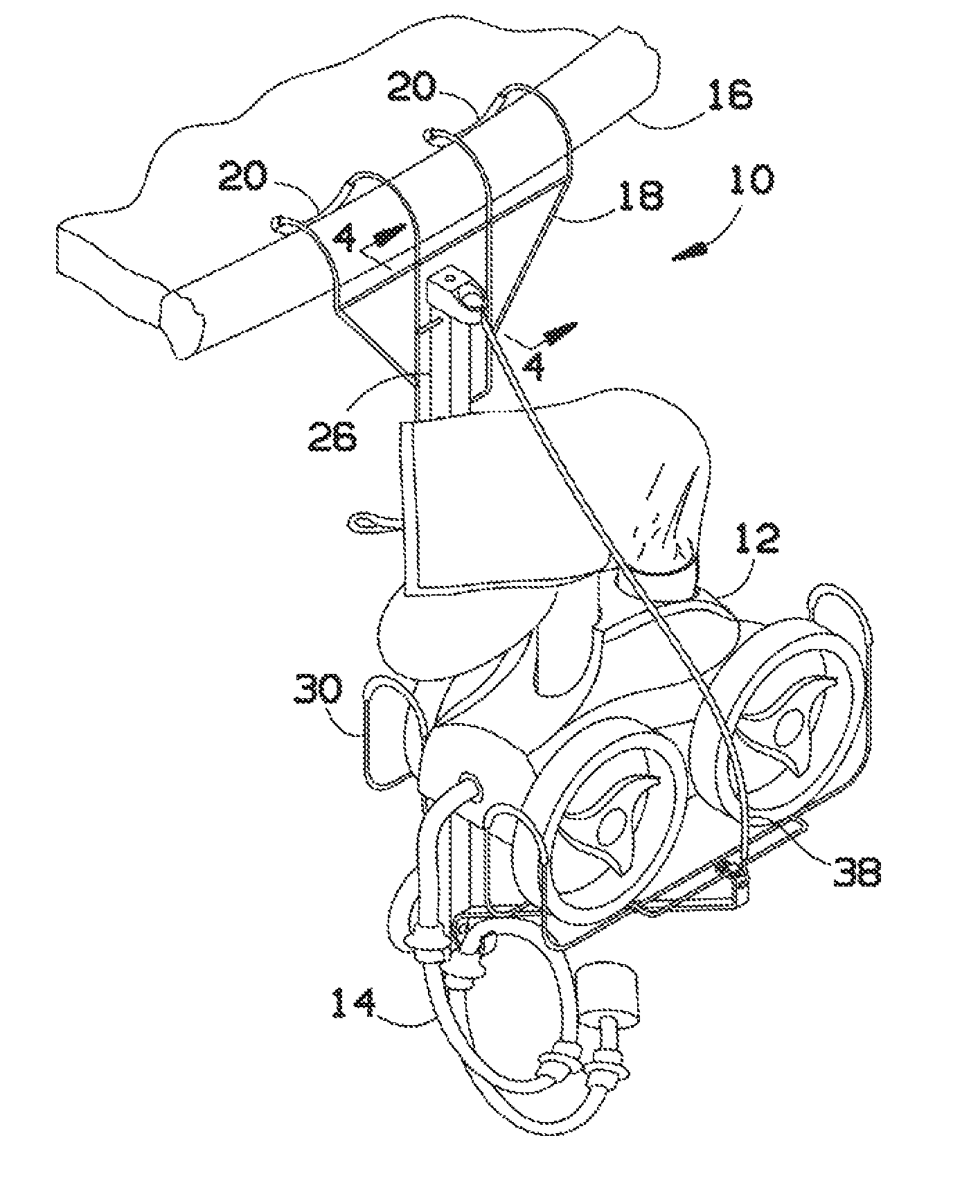
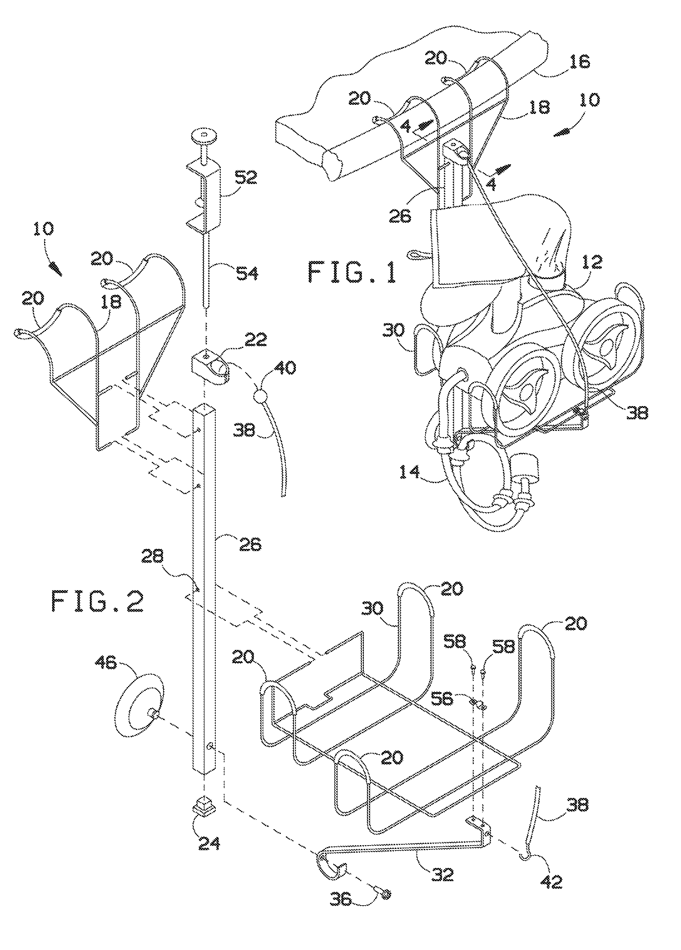
[0018]Broadly, embodiments of the present invention generally provide a pool caddy apparatus for stowing portions of an automatic pool cleaner to allow the pool cleaner to be set aside an not interfere with use of a pool.

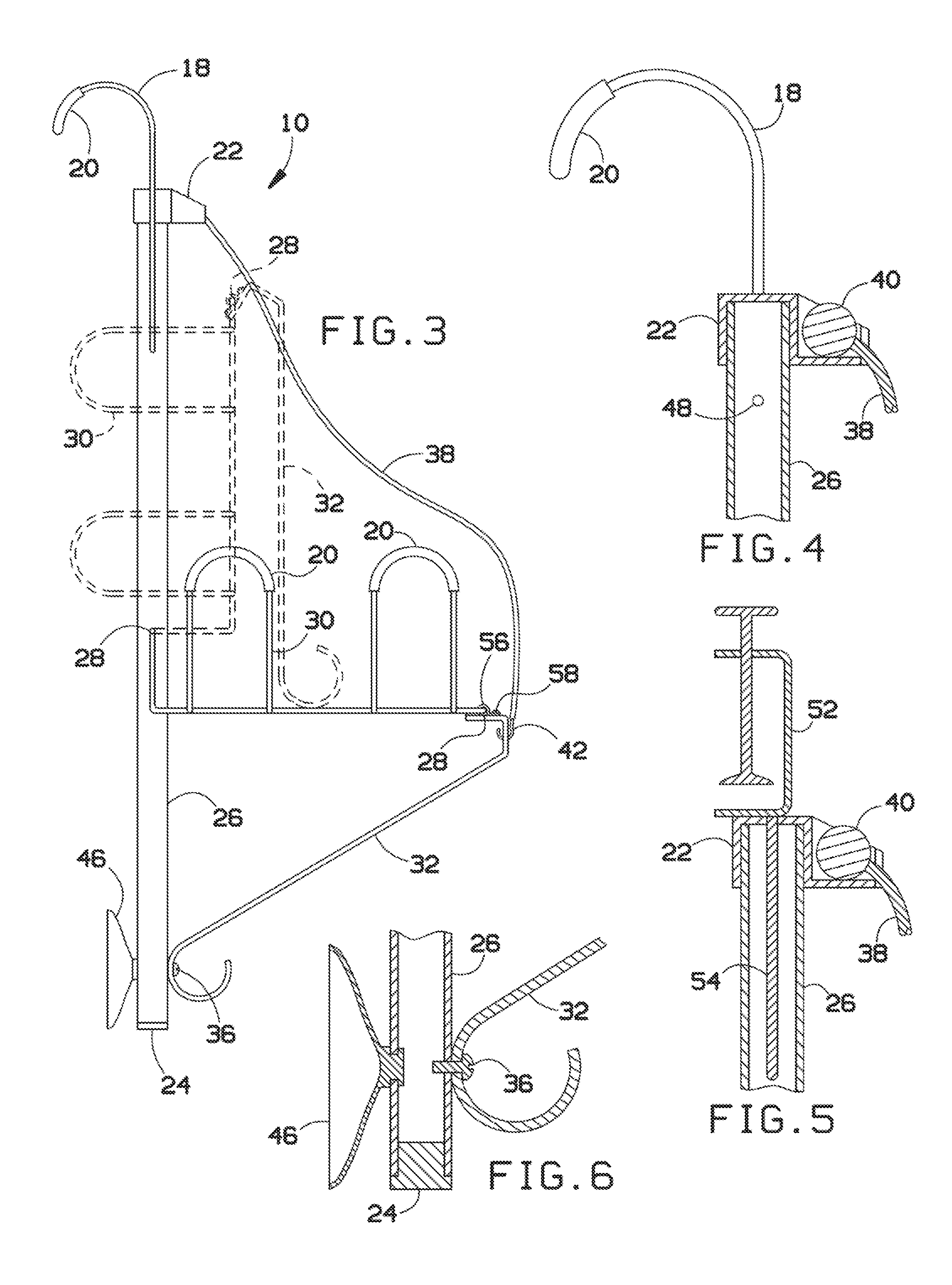
[0019]Referring to FIGS. 1-6, a pool caddy 10 may include support tube 26, which may have a wire deck hook 18 assembled thereto, a ball catch end cap 22 on a top end thereof, an end cap 24 on a bottom end thereof, a wire basket 30 assembled thereto, a suction cup 46 assemb...


PUM


Abstract

A pool caddy for stowing an automatic pool cleaner includes a support tube for providing structural support to the pool caddy. A deck mount disposed on the support tube secures the pool caddy to a pool deck edge. A container disposed on the support tube is configured to hold the automatic pool cleaner. A retainer disposed on the container is configured to secure the automatic pool cleaner to the container and to the support tube. A suction cup disposed on the support tube secures the pool caddy to a pool surface.

Description

BACKGROUND OF THE INVENTION[0001]The present invention generally relates to apparatus for operating pool systems, maintaining pool systems, and, more particularly, to an apparatus for stowing an automatic pool cleaner.[0002]Some pools utilize automatic pool cleaners to traverse pool surfaces or to skim the water surface to automatically scrub the pool and collect debris. Automatic pool cleaners provide a convenience of clean pools with minimum effort, but include hoses and skimming or scrubbing devices that may interfere with an enjoyment of the pool. Devices do not allow a user to pick up an automatic pool cleaner and quickly stow it to a side of the pool, while allowing the automatic pool cleaner to remain on.[0003]As can be seen, there is a need for an apparatus for stowing an automatic pool cleaner to a pool edge or deck.SUMMARY OF THE INVENTION[0004]In one aspect of the present invention, a pool caddy comprises a support tube; a deck hook disposed on a top of the support tube; ...

Claims


Application Information

Patent Timeline
Patent Type & Authority Patents(United States)
IPC IPC(8): F16B45/00
CPCE04H4/14E04H4/1654
Inventor BRASELL, JAMES MICHAELBRASELL, SANDRA LEEBRASELL, JUSTIN MICHAEL
Owner BRASELL JAMES M
Why Eureka
Try Eureka