
Building anchor systems

a technology for building anchors and systems, applied in the direction of rod connections, cables for vehicles/pulleys, structural elements, etc., can solve the problems of unsuitability for use in buildings requiring disguised reinforcement, risk of breaking, etc., and achieve the effect of preventing or inhibiting catastrophic structural failure of the surrounding building structur

Active Publication Date: 2014-08-19
CINTEC INT
View PDF6 Cites 15 Cited by
  • Summary
  • Abstract
  • Description
  • Claims
  • Application Information

AI Technical Summary

Benefits of technology

The present invention aims to provide a building anchor system that can withstand minor earthquakes and prevent damage to building structures during major earthquake events. The system includes elongate anchor rods and coupling joints that can non-elastically extend to prevent or inhibit catastrophic structural failure. The technical effect of this invention is to strengthen and protect building structures from damaging earthquake events.

Problems solved by technology

Whilst this method of reinforcement is an improvement over prior art anchoring systems which retain their rigidity and hence suffer the risk of breaking laterally, it is unsuitable for use in buildings requiring disguised reinforcement with minimal intrusion such as, in particular, in ancient buildings and monuments, where the preferred form of reinforcement is by drilling a relatively small diameter hole along e.g. the length of a wall to be reinforced by means of a steel anchor with thrust plates at each end which may be adjustable to increase or decrease the tension within the anchor to suit the circumstances.

Method used


Image

  • Building anchor systems
  • Building anchor systems

Examples


Embodiment Construction

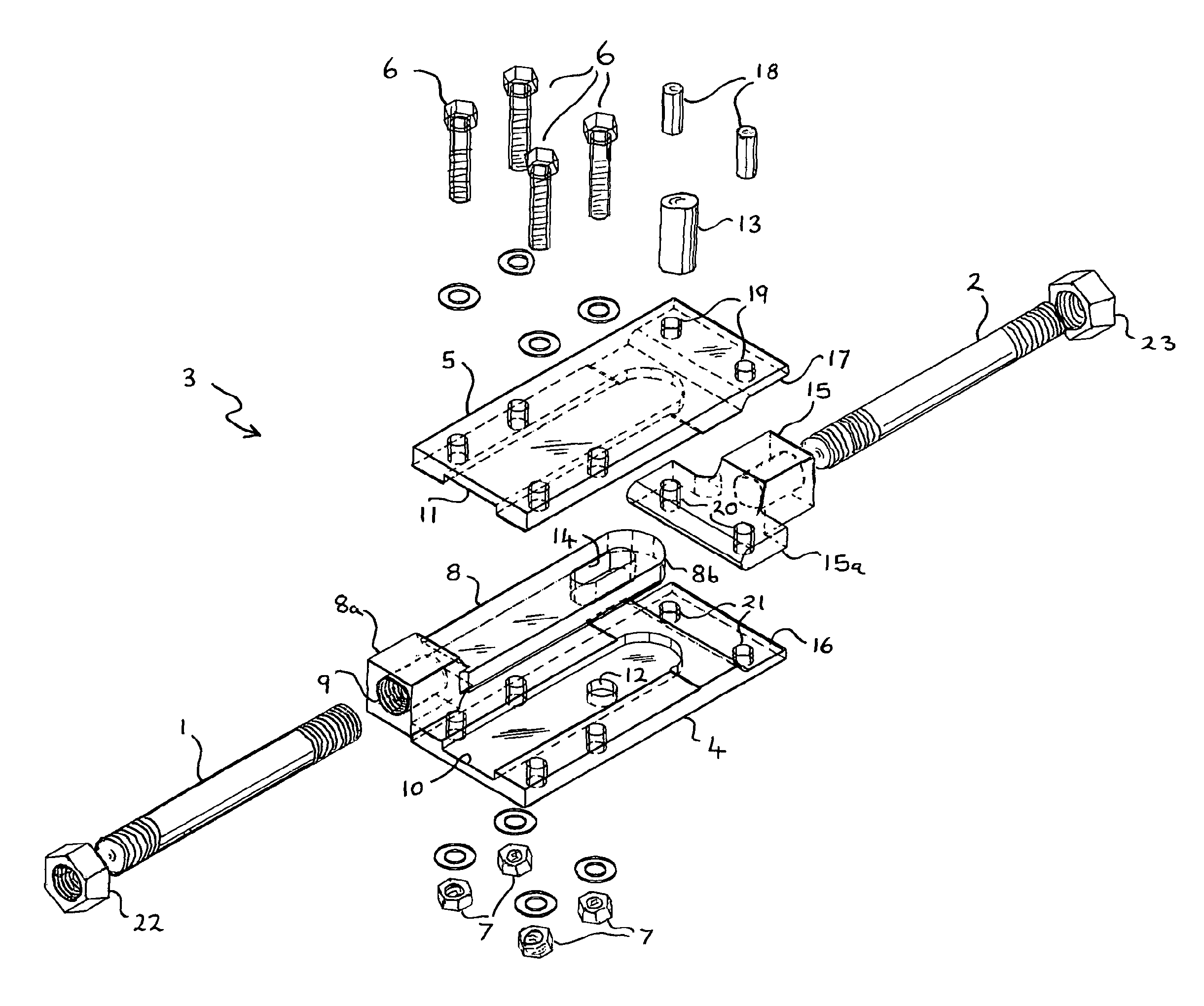
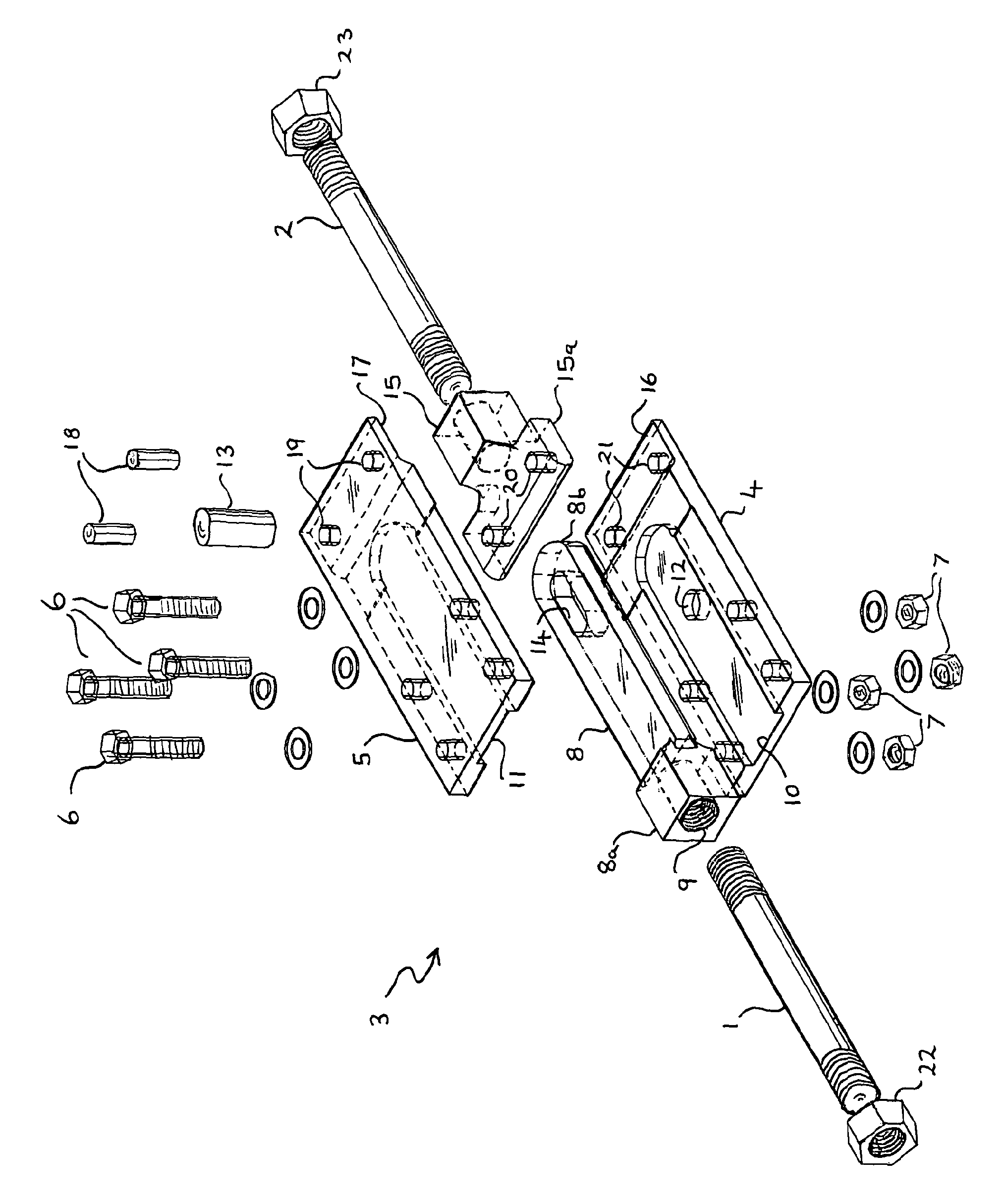
[0015]In the drawing, a pair of threaded anchor rods 1,2 are disposed along their common major axis on either side of an anchor rod coupling joint shown generally at 3 which comprises a rectangular base plate 4, a top or cover plate 5 which, when each are joined together by the bolts 6 and nuts 7, define a sleeve into which a slideable arm 8 may be inserted. The free end 8a of the slideable arm 8 includes a threaded bore 9 for receiving the threaded end of the anchor rod 1.

[0016]The arm 8 has a rounded end 8b and is shaped to fit within correspondingly shaped, but collectively shallower, inwardly facing channels 10, 11 in the base plate 4 and cover 5. The combined depth of the channels 10, 11 is less than the thickness of the slideable arm 8 so that when the cover 5 plate is fitted onto the base plate 4 and the bolts 6 and nuts 7 are tightened they each become an interference fit over the arm 8 and, depending upon the torque applied to the bolts and nuts 6, 7 the frictional force ne...


PUM


Abstract

A building anchor system includes a pair of elongate anchor rods (1,2), an anchor rod coupling joint (3) for joining the anchor rods end-on-end, the anchor rod coupling joint comprising or including a sleeve (4, 5, 6&7) for connection to an end of one of the anchor rods (1) a slideable arm (8) receivable in the sleeve for connection to an end of the other anchor rod (2) a closed slot within the arm or sleeve for slideably receiving the free end of a stop member (13) by which movement of the anchor rods along their major axis is possible to the extent allowed by the length of the slot, and frictional adjustment means (6,7) acting between the arm and the sleeve by which they may be joined and by which the force required to move them with respect to each other can be selectively varied. The invention also extends of a method of preventing or inhibiting catastrophic structural failure of a building by installing one or more anchor systems of the type described.

Description

FIELD OF THE INVENTION[0001]This invention relates to building anchor systems of the type that use anchor rods which are typically used to reinforce structural parts of buildings, such as walls, and in particular structural parts of old buildings which may otherwise be prone to damage from e.g. earthquakes or ground settlement.BACKGROUND OF THE INVENTION[0002]A building anchor typically comprises an elongate rod threaded at both ends so that it may be inserted within a hole formed along the length of a wall of a structure such as a building and onto which thrust plates may be then fitted and tightened by nuts to tension the anchor and thereby strengthen the wall against failure. Where the building is generally box-like two or more such anchors are secured between corners of the building along each wall, thereby considerably stiffening it and decreasing the likelihood of structural failure in the event of an earthquake or other such vibrational event. However, a problem with this kno...

Claims


Application Information

Patent Timeline
IPC IPC(8): E04G23/02E04C5/00E04B1/41E04B1/38
CPCE04B1/4157E04G23/0218E04G23/0222Y10T403/7045Y10T403/5706Y10T403/75
Inventor JAMES, PETERLEE, DENNISPAGANONI, SARAD'AYALA, DINA
Owner CINTEC INT
Learn More