
Separator for non-aqueous electrolyte secondary battery and non-aqueous electrolyte secondary battery using the same
a technology of electrolyte secondary battery and electrolyte secondary battery, which is applied in the direction of cell seperators/membranes/diaphragms/spacers, electrical devices, cell components, etc., can solve the problems of battery reaction stopping, battery temperature might increase abruptly, and loss of ion conductivity between electrodes, etc., to achieve better understanding, the effect of favorable capacity retention rate in charge/discharge cycles
- Summary
- Abstract
- Description
- Claims
- Application Information
AI Technical Summary
Benefits of technology
Problems solved by technology
Method used
Image

Examples
example 1
(1) Production of Positive Electrode 5
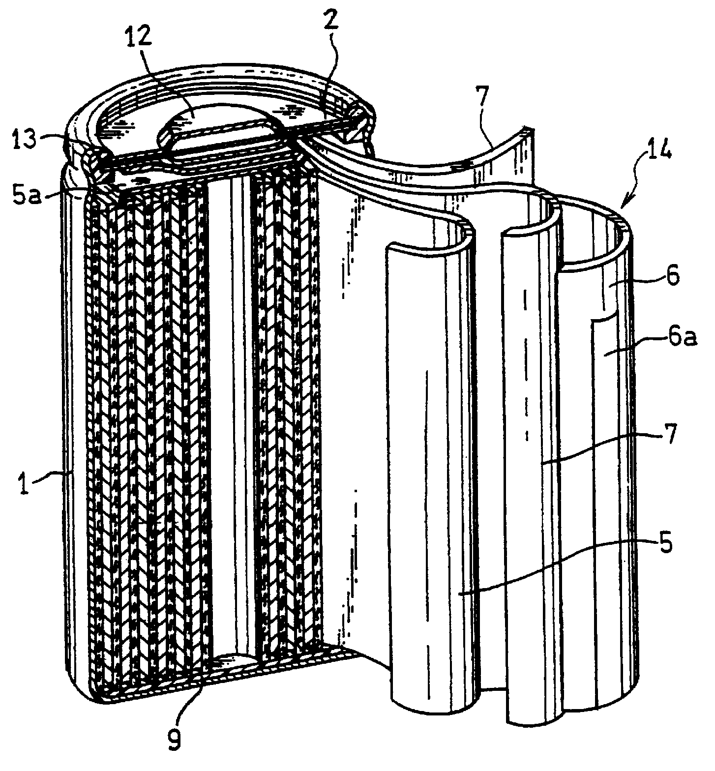
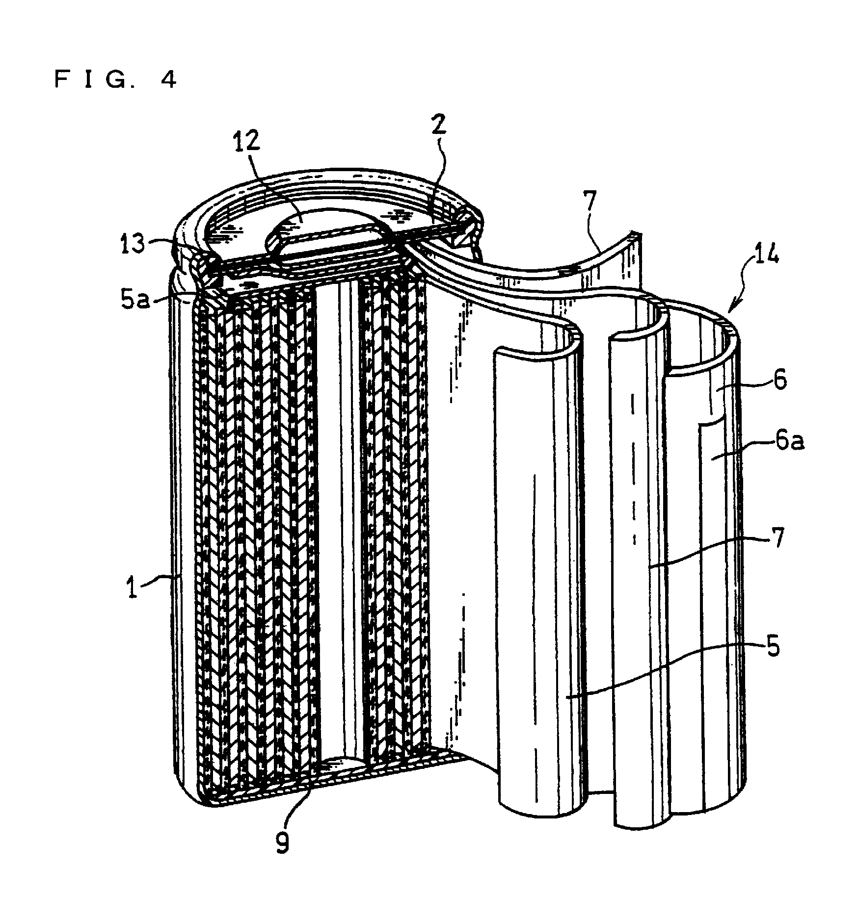
[0117]To an appropriate amount of N-methyl-2-pyrrolidone, 100 parts by mass of lithium cobalt oxide serving as the positive electrode active material, 2 parts by mass of acetylene black serving as the conductive agent, and 3 parts by mass of polyvinylidene fluoride resin serving as the binder were added and kneaded, to prepare a material mixture in the form of slurry. The slurry was continuously applied onto both surfaces of a belt-like aluminum foil (thickness: 15 μm) serving as the positive electrode current collector. Here, a portion was left uncoated with the slurry, so that the portion can serve as an aluminum foil-exposed portion for connecting a positive electrode lead 5a thereto. The material mixture was dried, and films of the material mixture were rolled together with the positive electrode current collector two to three times at a line pressure of 1,000 kgf / cm (9.8 kN / cm) until the thickness of the films reached 180 μm, whereby positi...
example 2
[0137]Batteries were fabricated in the same manner as in Example 1 except that the below-described separators were used.
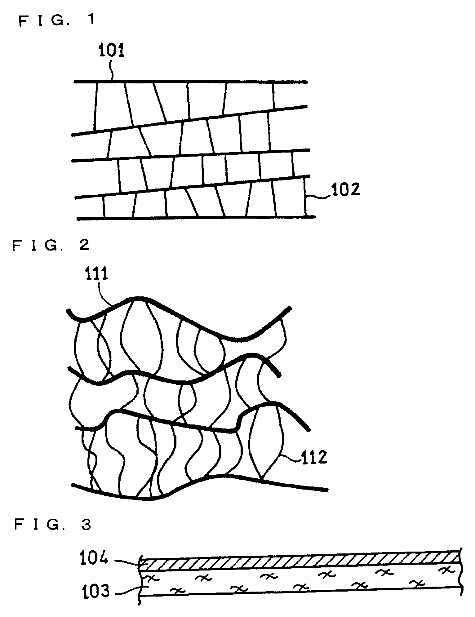
[0138]First, various polyethylene porous films in which the average distance between adjacent extended-chain crystals was 3.0 μm or more and less than 5.0 μm and the average distance between adjacent folded-chain crystals was 0.5 μm or more and less than 0.7 μm (the same structure as that of No. 6 in Table 1) were fabricated. The thickness of the polyethylene porous film was set to 20 μm or 17 μm. With regard to the 20-μm-thick polyethylene porous films, the conditions of production process were changed as appropriate so that the resultant films had different Gurley values and porosities, while having the same structure as that of No. 6 in Table 1, and several types of polyethylene porous films were produced.
[0139]On the other hand, an NMP solution of aramid was applied onto one surface of each of the 17-μm-thick polyethylene porous films. In such a manner, two-lay...
PUM
| Property | Measurement | Unit |
|---|---|---|
| distance | aaaaa | aaaaa |
| distance | aaaaa | aaaaa |
| distance | aaaaa | aaaaa |
Abstract
Description
Claims
Application Information