Strain relief device

a strain relief and sealing technology, applied in the direction of coupling device connections, cables, insulated conductors, etc., can solve the problems of inconsistent seal reliability and become more difficult to form a reliable environmental seal, and achieve the effect of convenient mounting the retention devi

Inactive Publication Date: 2014-08-26
CORNING RES & DEV CORP
View PDF20 Cites 30 Cited by
  • Summary
  • Abstract
  • Description
  • Claims
  • Application Information

AI Technical Summary

Problems solved by technology

Thus, the reliability of the seal can be inconsistent from one installer to another.
Further, as the number of cables increases, it becomes more difficult to form a reliable environmental seal.

Method used


Image

  • Strain relief device
  • Strain relief device
  • Strain relief device

Examples


Embodiment Construction

[0026]In the following Detailed Description, reference is made to the accompanying drawings, which form a part hereof, and in which is shown by way of illustration specific embodiments in which the invention may be practiced. In this regard, directional terminology, such as “top,”“bottom,”“front,”“back,”“leading,”“forward,”“trailing,” etc., is used with reference to the orientation of the Figure(s) being described. Because components of embodiments of the present invention can be positioned in a number of different orientations, the directional terminology is used for purposes of illustration and is in no way limiting. It is to be understood that other embodiments may be utilized and structural or logical changes may be made without departing from the scope of the present invention.

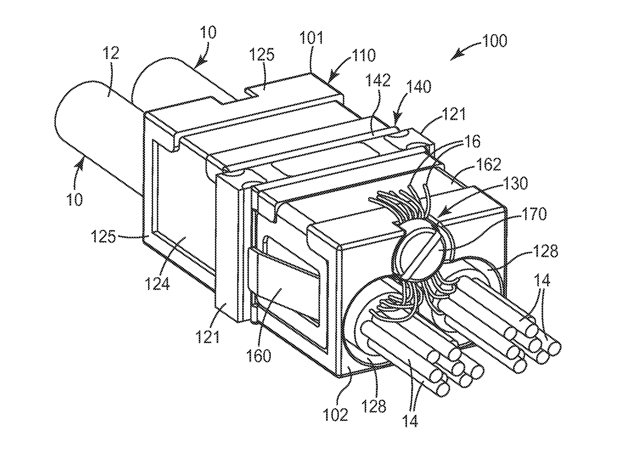
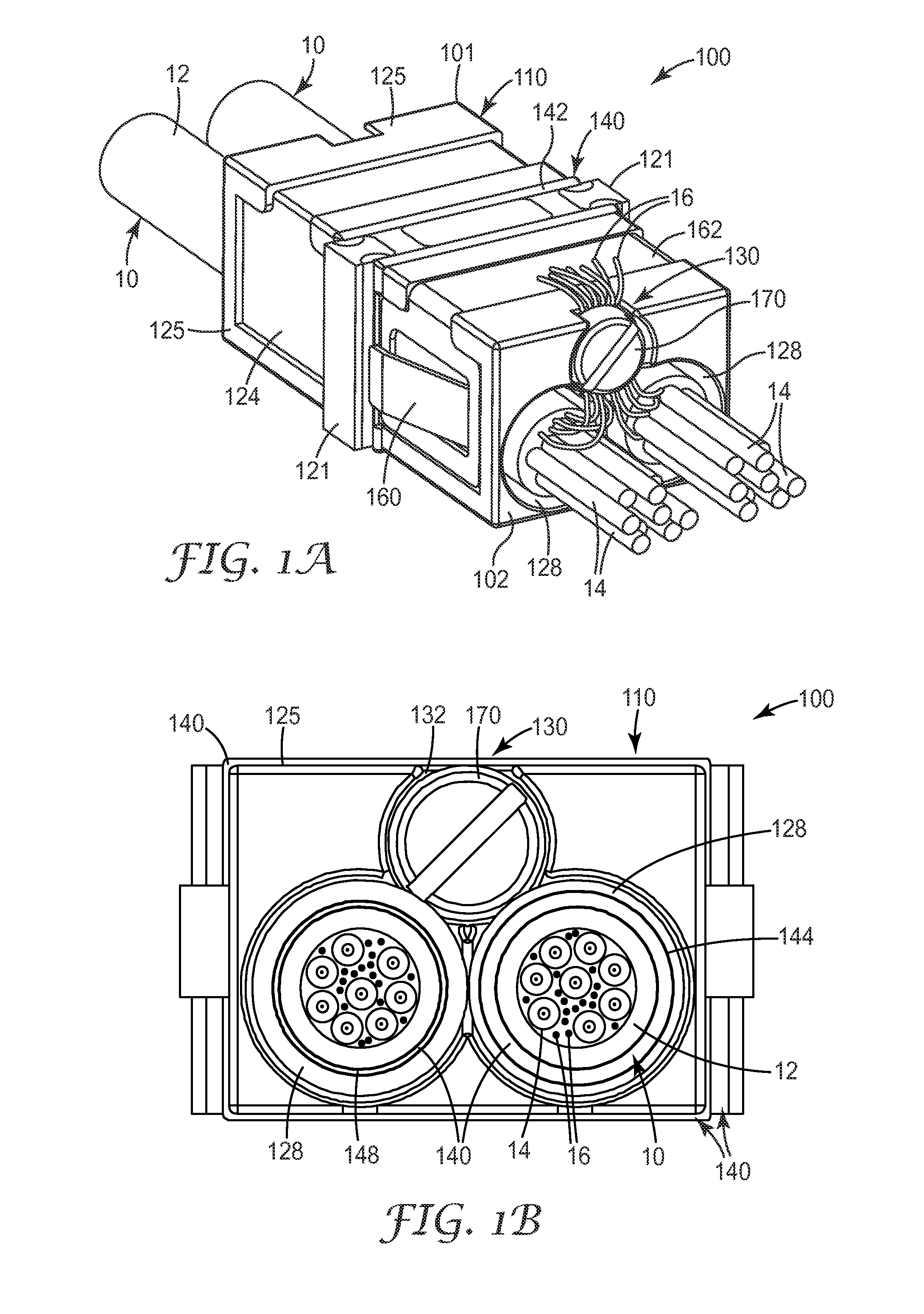
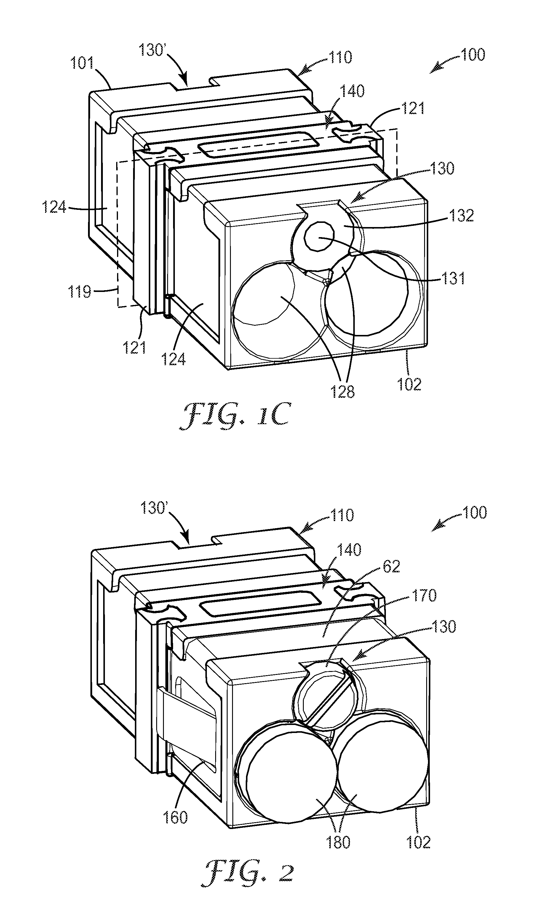
[0027]The present invention is directed to a strain relief device for use in a telecommunication enclosure or patch panel to provide strain relief and an environmental seal (e.g. protection against the in...


PUM


Abstract

A strain relief device is disclosed that allows the passage of at least one telecommunication cable therethrough. The exemplary strain relief device has a one-piece, rectangular tubular body, an external strength member securing section to secure strength members from the at least one telecommunication cable to the rectangular tubular body and a sealing member to provide an environmental seal between the at least one telecommunication cable and the strain relief device and between the strain relief device and a mounting structure into which the strain relief device is inserted. The rectangular tubular body has an outer surface and at least one cable channel extending between a first end of the rectangular tubular body and a second end rectangular tubular body.

Description

BACKGROUND[0001]1. Field of the Invention[0002]The present invention generally relates to an environmentally sealed strain relief device for use in a telecommunication enclosure, and more particularly to a device for securing up to two telecommunication cables in an industry standard footprint.[0003]2. Description of the Related Art[0004]Cables, such as telecommunication cables and electrical power distribution cables, are ubiquitous and used for distributing electrical power and all manner of data signals across vast networks. The majority of cables are electrically conductive cables (typically copper), although the use of optical fiber cables is growing rapidly in telecommunication systems as larger and larger amounts of data are transmitted. As cables are routed across power or data networks, it is necessary to periodically open, connect, or splice the cable so that power or data may be distributed to other cables or “branches” of the network. The cable branches may be further di...

Claims


Application Information

Patent Timeline
Patent Type & Authority Patents(United States)
IPC IPC(8): H02G3/00G02B6/44H02G15/007
CPCH02G3/26G02B6/4477H02G15/007
Inventor PIMENTEL, NELSON, GONCALVES
Owner CORNING RES & DEV CORP
Why Eureka
Try Eureka