Forward locking pull pin

a pull pin and forward locking technology, applied in the direction of fastening means, rod connections, basic electric elements, etc., can solve the problems of limiting the usefulness and longevity of the adjustment material, the surface surrounding the hole may become beveled, and the hole on the second material may become worn and misshaped

Active Publication Date: 2014-09-02
PIVOT POINT
View PDF37 Cites 16 Cited by
  • Summary
  • Abstract
  • Description
  • Claims
  • Application Information

AI Technical Summary

Problems solved by technology

Pull pins are well-known in the art, however, present pull pin designs have some deficiencies which limit their usefulness and longevity.
For example, in time, the holes on the adjusting material (the second material) may become worn and misshaped.
Furthermore, the surfaces surrounding the hole may become beveled.

Method used


Image

  • Forward locking pull pin
  • Forward locking pull pin
  • Forward locking pull pin

Examples


Embodiment Construction

[0042]Although the disclosure hereof is detailed and exact to enable those skilled in the art to practice the invention, the physical embodiments herein disclosed merely exemplify the invention which may be embodied in other specific structures. While the preferred embodiment has been described, the details may be changed without departing from the invention, which is defined by the claims.

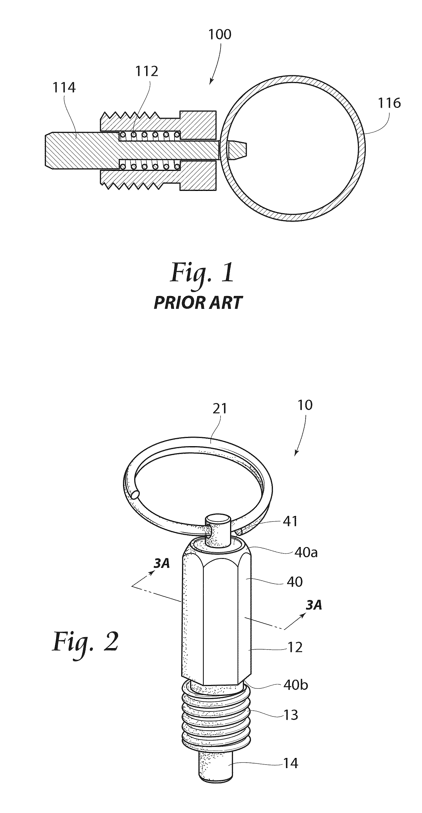
[0043]FIG. 1 shows a prior art pull pin 100 discussed above. As shown, the pull pin 100 is biased in a forward direction by spring 112. Just as the pin shaft 114 can be retracted by pulling on ring 116, so too can the shaft 114 be retracted by a pushing force directly on pin shaft 114. The prior art pull pin 100 has no mechanism to retain the pull pin shaft 114 in the forward position shown in the figure, therefore allowing other forces to act on pin shaft 114 and potentially release the pull pin accidentally.

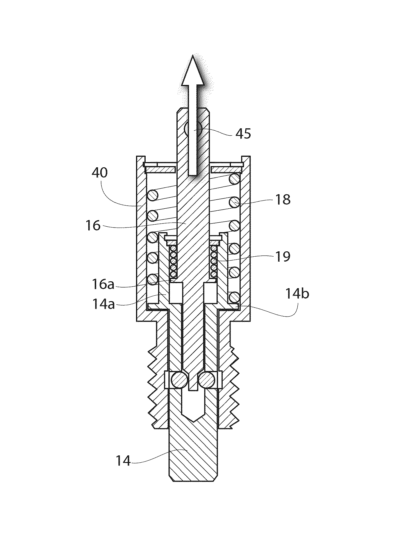
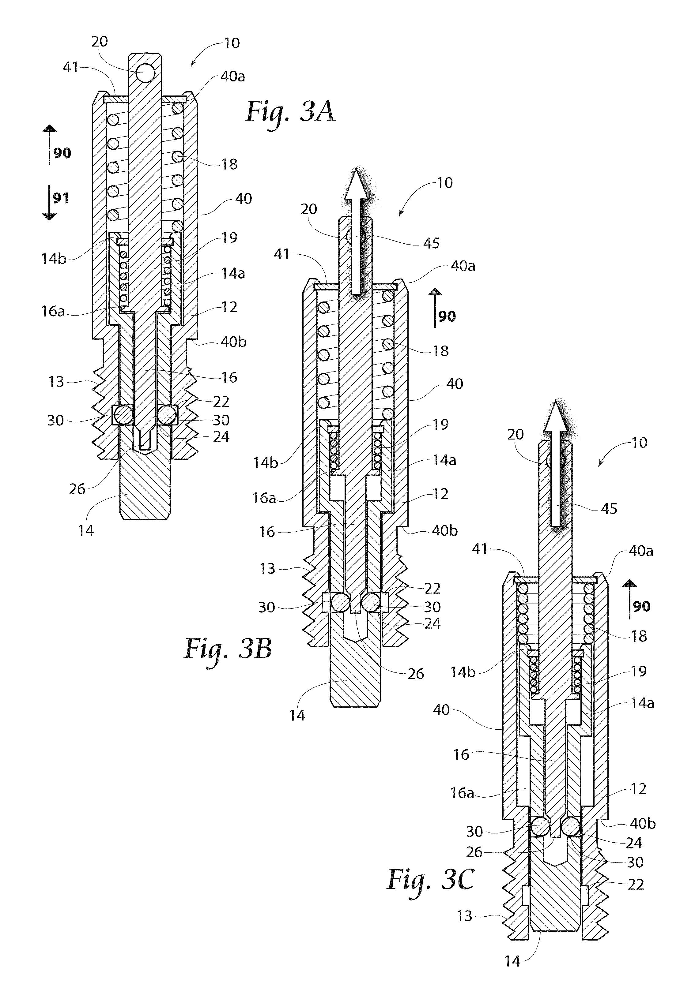
[0044]FIGS. 2 and 3A-3C show one embodiment of the forward locking pull pin 10 according ...


PUM


Abstract

A pull pin is configured to lock in a forward position to prevent accidental or undesirable retraction of the pull pin. The pull pin has a housing, a pull pin shaft, an inner shaft, a first and second spring, and at least one ball bearing. The housing has a ball locking space, which holds the ball bearing between the locking space and a ball aperture formed in the pull pin shaft to thereby lock the pull pin shaft in the forward position. Only upon the application of an external force to the inner shaft, which aligns a ball release portion with the ball aperture, can the ball bearing move into the ball release portion and thereby move out of said locking space, allowing for the retraction of the pull pin shaft.

Description

BACKGROUND OF THE INVENTION[0001]The present invention relates generally to non threaded fasteners that may be used to adjustably attach two materials or items. In particular, the present invention relates to pull pins that lock in a forward position. Pull pins are generally used for applications where items or materials slide proximal to one another and adjustments are made as to their positioning relative to each other. Some applications for pull pins may include telescopic legs having adjustable heights, adjustable tubing, and safety gates having adjustable widths, as an example. A pull pin is generally threaded through a hole in a first surface or material, with the pin shaft portion extending through a hole in the second material. The second material generally has a plurality of spaced apart holes. The pull pin shaft may be pulled by a handle or other pulling mechanism to retract the pin from a first hole in the second material, thereby releasing the material and allowing for a...

Claims


Application Information

Patent Timeline
Patent Type & Authority Patents(United States)
IPC IPC(8): F16B21/00
CPCF16B2/16F16B7/105Y10T403/7088Y10T403/592
Inventor BAUS, ROMY
Owner PIVOT POINT
Why Eureka
Try Eureka