
Small footprint scissor suspension mechanism

a suspension mechanism and small-scale technology, applied in the direction of chairs, machine supports, other domestic objects, etc., can solve the problems of reducing the elevation range and/or extending the external side dimensions, and the efficiency of the suspension may be an important issu

Inactive Publication Date: 2014-09-30
CREATIONS I D B05 INC
View PDF36 Cites 8 Cited by
  • Summary
  • Abstract
  • Description
  • Claims
  • Application Information

AI Technical Summary

Benefits of technology

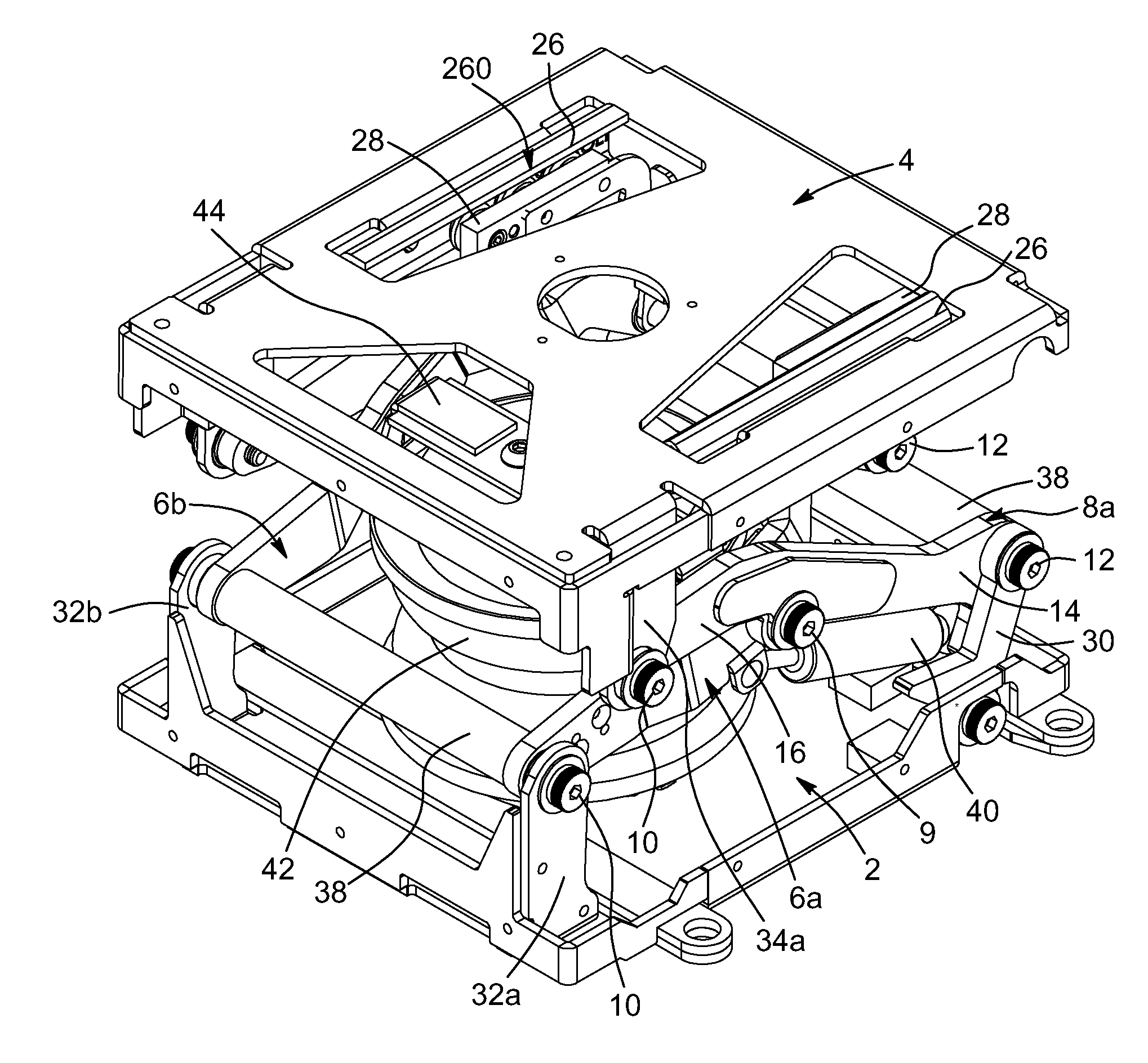
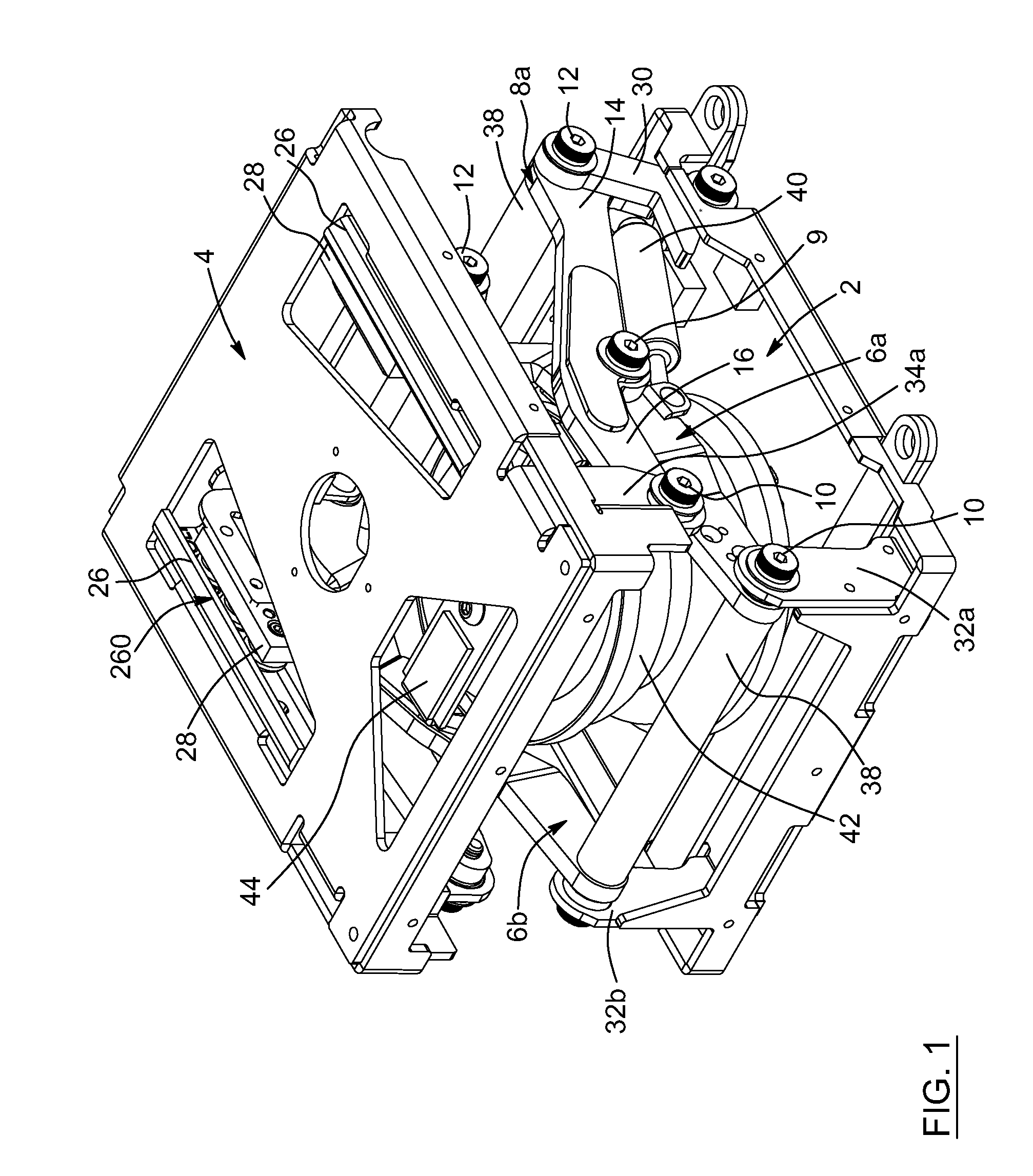
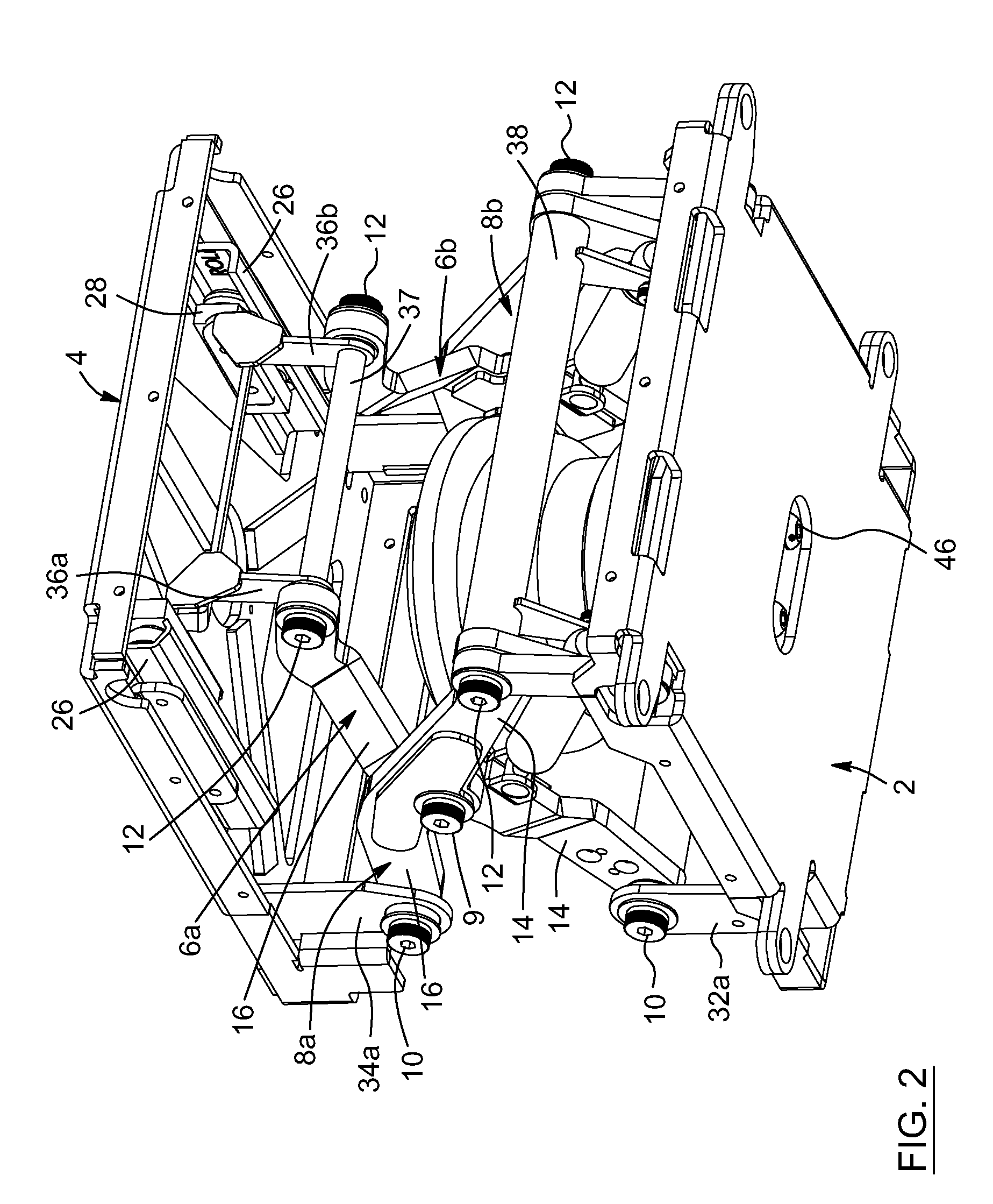
The patent text describes an improved linkage assembly for a scissor suspension system. The linkage assembly includes a set of two pairs of symmetrically opposing translational linkages that connect each of the corresponding four translational pivot interfaces to either the base element or the movable element. This reduces the vertical position variation of the translational pivot interfaces. Additionally, each of the first and second scissor arms have a curved side surface that creates an inflexion point proximate to the central pivot interface. This helps to avoid mutual interference of parts of the scissor suspension when the movable element is displaced relative to the base element. These technical effects improve the performance and efficiency of the scissor suspension system.

Problems solved by technology

However, known scissor suspensions achieving height compactness in the lowest position of the upper frame may have a reduced elevation range and / or enlarged external side dimensions.
In the field of railroad freight and transit, efficiency of suspensions may be an important issue due to whole body vibration.

Method used


Image

  • Small footprint scissor suspension mechanism
  • Small footprint scissor suspension mechanism
  • Small footprint scissor suspension mechanism

Examples


Embodiment Construction

[0044]In the following description, the same numerical references refer to similar elements. Furthermore, for the sake of simplicity and clarity, namely so as not to unduly burden the figures with several reference numbers, only certain figures have been provided with reference numbers, and components and features of the present invention illustrated in other figures can be easily inferred therefrom. The embodiments, geometrical configurations, and / or dimensions shown in the figures are preferred for exemplification purposes only.

[0045]Moreover, although the present invention was primarily designed for a scissor mechanism suspension for a seat, for example, it may also be used in other fields, as apparent to a person skilled in the art. For this reason, expressions such as “vehicle”, “seat”, etc., as used herein should not be taken as to limit the scope of the present invention and includes all other kinds of materials, objects and / or purposes with which the present invention could ...


PUM


Abstract

A scissor suspension mechanism, optionally used as a seat base, comprising both small footprint base and movable element, a set of two pairs of crossed first and second scissor arms and a linkage assembly including a plurality of pivot interfaces and linkages; which are designed in a way that the crossed first and second scissor arms describe, during the total elevation stroke of the movable element with respect to the base element, both positive and negative angles with respect to each other while passing through a null angle at which the overall mechanism length is maximal.

Description

FIELD OF THE INVENTION[0001]The present invention generally relates to scissor suspension mechanisms. More particularly, the present invention relates to a scissor suspension mechanism which has a geometry enabling extended total elevation stroke while keeping reduced external side dimensions compared to known mechanisms.BACKGROUND OF THE INVENTION[0002]Known scissor suspensions provide multiple advantages over straight linear suspensions. Such scissor suspensions are mentioned in various patent documents: U.S. Pat. No. 4,856,763, US 2010 / 0133413, U.S. Pat. No. 4,913,482, U.S. Pat. No. 5,169,112, U.S. Pat. No. 4,943,037, U.S. Pat. No. 5,927,679, U.S. Pat. No. 5,364,060, U.S. Pat. No. 5,975,508, U.S. Pat. No. 5,984,410 and U.S. Pat. No. 6,264,163. In addition, some patent documents relate to scissor suspension mechanisms: US 2007 / 0295882, US 2008 / 0156960, U.S. Pat. No. 3,853,296 and U.S. Pat. No. 5,222,709.[0003]Known mechanisms have a scissor geometry by including a base frame, an u...

Claims


Application Information

Patent Timeline
Patent Type & Authority Patents(United States)
IPC IPC(8): F16M13/00B60N2/50B60N2/52
CPCB60N2/508B60N2/525
Inventor ARCHAMBAULT, ETIENNE
Owner CREATIONS I D B05 INC
Learn More