Detachable vehicle taillight and flashlight combination
What is AI technical title?
AI technical title is built by PatSnap AI team. It summarizes the technical point description of the patent document.
a taillight and flashlight technology, applied in the direction of vehicles carrying long loads, transportation and packaging, instruments, etc., can solve the problems of loss of bumper protection, more difficult to recognize when the tailgate is in a horizontal position, so as to improve reliability
Inactive Publication Date: 2014-10-07
HERTZ ALLEN D +1
View PDF25 Cites 13 Cited by
Summary
Abstract
Description
Claims
Application Information
AI Technical Summary
This helps you quickly interpret patents by identifying the three key elements:
Problems solved by technology
Method used
Benefits of technology
Benefits of technology
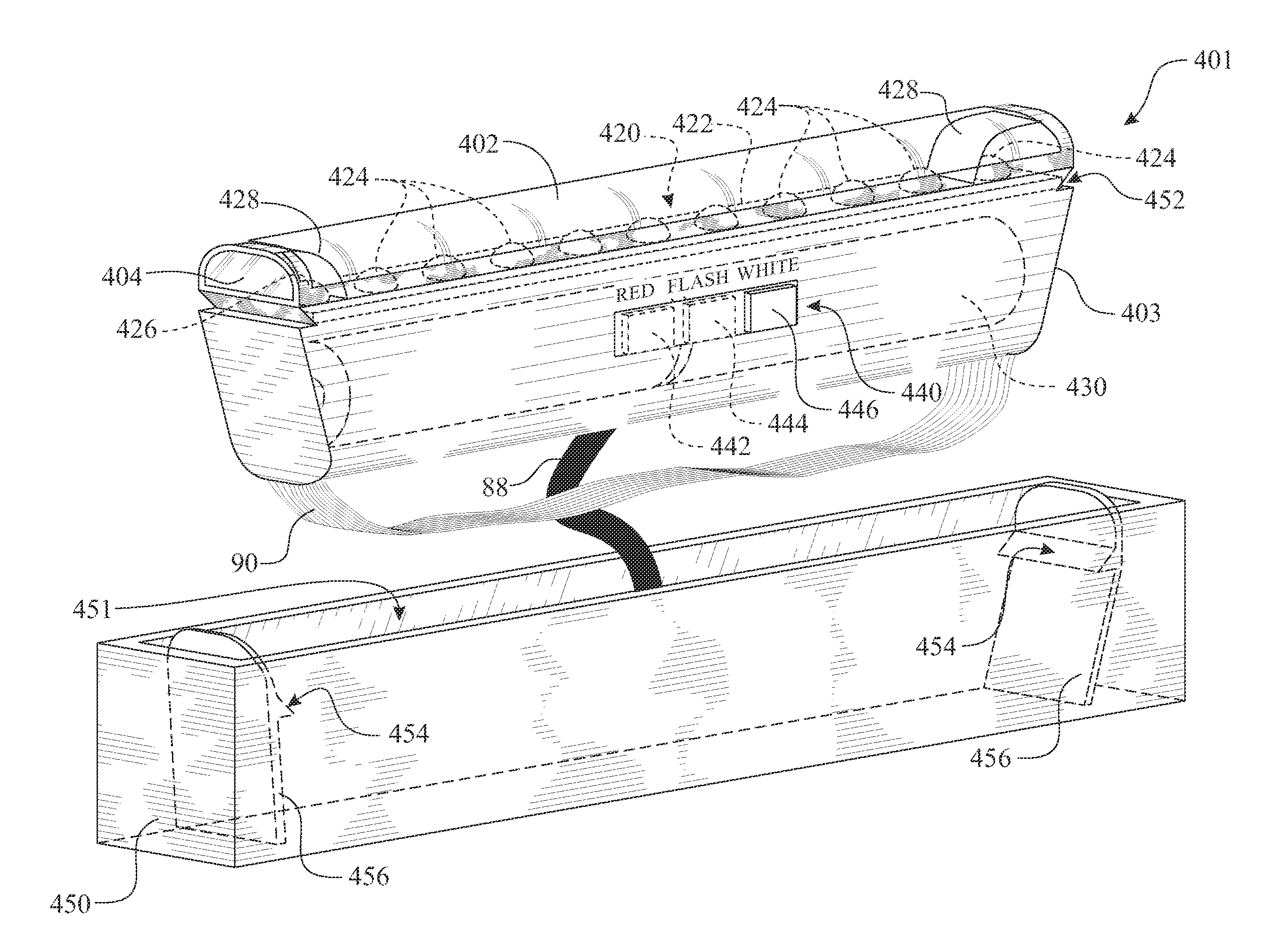
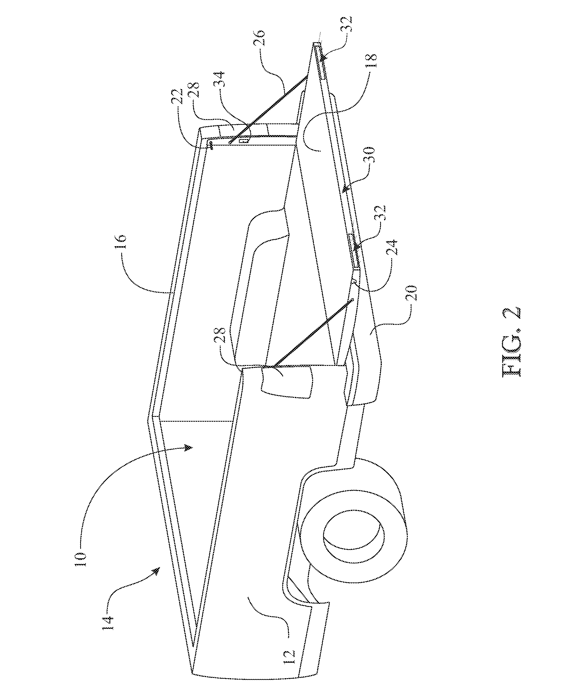
[0026]A seventeenth aspect of the present invention utilizes a temporary holding mechanism to temporarily hold the light in the desired position. An example secures the rotating portion of the safety light in a vertical position when the tailgate is in a horizontal position, thus maintaining the light steady over bumps.
[0032]A twenty-third aspect of the present invention is the utilization of reflectors behind an illumination source to assist in directing the highest light intensity output.
[0053]A forty-fourth aspect of the present invention is an assembly process of potting at least one LED to improve reliability.
Problems solved by technology
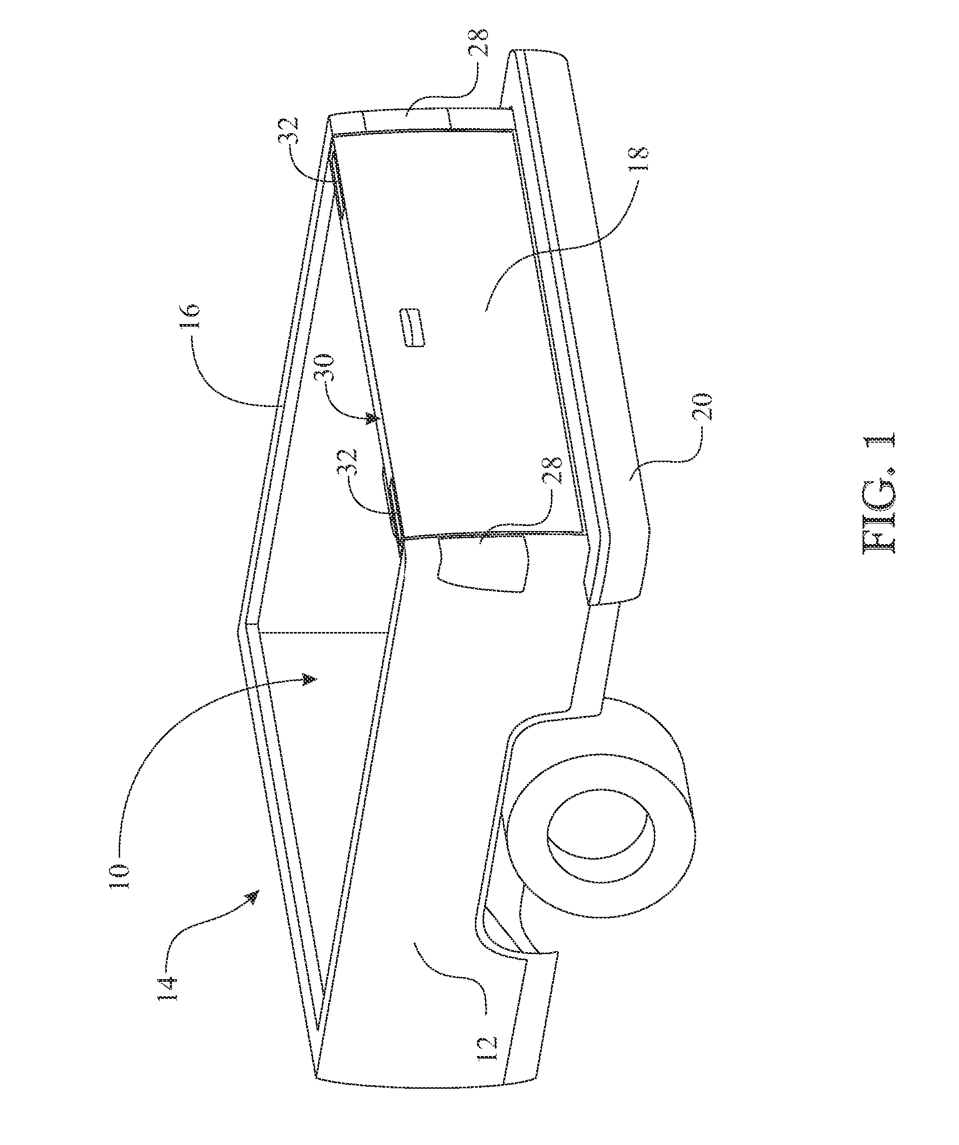
Several issues arise when positioning the tailgate of a pickup truck in a horizontal position.
The first issue is the loss of protection by the bumper.
Another being the potential for an accident wherein a vehicle behind the pickup truck would run into the carried load or the horizontal tailgate.
On darker color trucks, it is more difficult to recognize when a tailgate is in a horizontal position at night.
On a lighter color truck, it is more difficult to recognize when a tailgate is in a horizontal position during daylight.
The teachings need to be removable as it is highly susceptible to damage when loading cargo into the pickup bed, as it is taught to be an elevated object.
Method used
Image
Click on the blue label to locate the original text in one second.
Reading with bidirectional positioning of images and text.
Examples
Embodiment Construction
[0094]The following detailed description is merely exemplary in nature and is not intended to limit the described embodiments or the application and uses of the described embodiments. As used herein, the word “exemplary” or “illustrative” means “serving as an example, instance, or illustration.” Any implementation described herein as “exemplary” or “illustrative” is not necessarily to be construed as preferred or advantageous over other implementations. All of the implementations described below are exemplary implementations provided to enable persons skilled in the art to make or use the embodiments of the disclosure and are not intended to limit the scope of the disclosure, which is defined by the claims. For purposes of description herein, the terms “upper”, “lower”, “left”, “rear”, “right”, “front”, “vertical”, “horizontal”, and derivatives thereof shall relate to the invention as oriented in FIG. 1. Furthermore, there is no intention to be bound by any expressed or implied theo...
PUM
Abstract
A safety light system integrated into a vehicle. The safety light system includes a safety light assembly receptacle carried by a body panel of a vehicle. The safety light assembly receptacle includes a light assembly receiving cavity for receiving and temporarily retaining a removable light assembly. The removable light assembly includes elements to provide a user controlled continuous red light, a flashing red light, and a continuous white light. The flashing red light provides a roadside flare configuration. The continuous white light provides a flashlight configuration. The continuous red light in conjunction with the flashing red light configuration provides a driving light configuration. The removable light assembly can include a securing mechanism for attaching the removable light assembly to an object to warn others of the extended object and / or support legs enabling operation as a roadside flare, spotlight, and the like.
Description
RELATED PATENT APPLICATION(S)[0001]This application is a Divisional patent application, which claims benefit to U.S. patent application Ser. No. 13 / 569,173, filed on Aug. 7, 2012 (Issuing as U.S. Pat. No. 8,552,852), which is a Continuation-In-Part Application claiming benefit to U.S. patent application Ser. No. 12 / 947,659 filed on Nov. 16, 2010 (Issued as U.S. Pat. No. 8,237,557 on Aug. 7, 2012), which is a Continuation-In-Part claiming benefit to Non-Provisional patent application Ser. No. 11 / 562,389 filed on Nov. 21, 2006 (Issued as U.S. Pat. No. 7,834,750 on Nov. 16, 2010), which is a Non-Provisional Application claiming priority to each of Provisional Patent Application Ser. No. 60 / 793,849 filed on Apr. 20, 2006, Provisional Patent Application Ser. No. 60 / 742,471 filed on Dec. 5, 2005, and Provisional Patent Application Ser. No. 60 / 739,069 filed on Nov. 22, 2005, all of which are incorporated herein by reference.FIELD OF THE INVENTION[0002]The present invention relates to a rem...
Claims
Application Information
Patent Timeline
Application Date:The date an application was filed.
Publication Date:The date a patent or application was officially published.
First Publication Date:The earliest publication date of a patent with the same application number.
Issue Date:Publication date of the patent grant document.
PCT Entry Date:The Entry date of PCT National Phase.
Estimated Expiry Date:The statutory expiry date of a patent right according to the Patent Law, and it is the longest term of protection that the patent right can achieve without the termination of the patent right due to other reasons(Term extension factor has been taken into account ).
Invalid Date:Actual expiry date is based on effective date or publication date of legal transaction data of invalid patent.

