
Book spine mounted book light

Active Publication Date: 2007-01-16
MAJOR WILLIAM ROBERT
View PDF28 Cites 27 Cited by
  • Summary
  • Abstract
  • Description
  • Claims
  • Application Information

AI Technical Summary

Benefits of technology

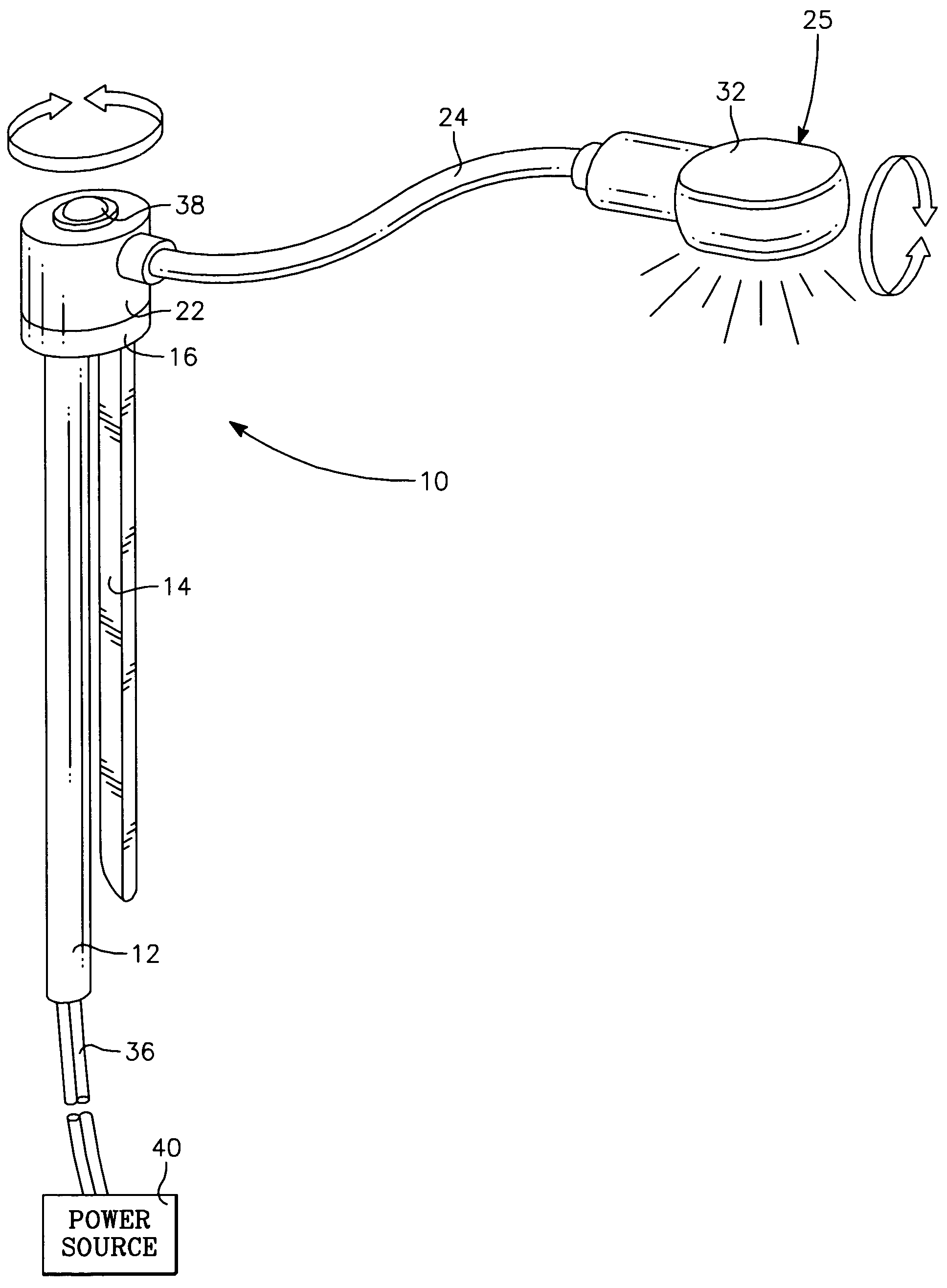
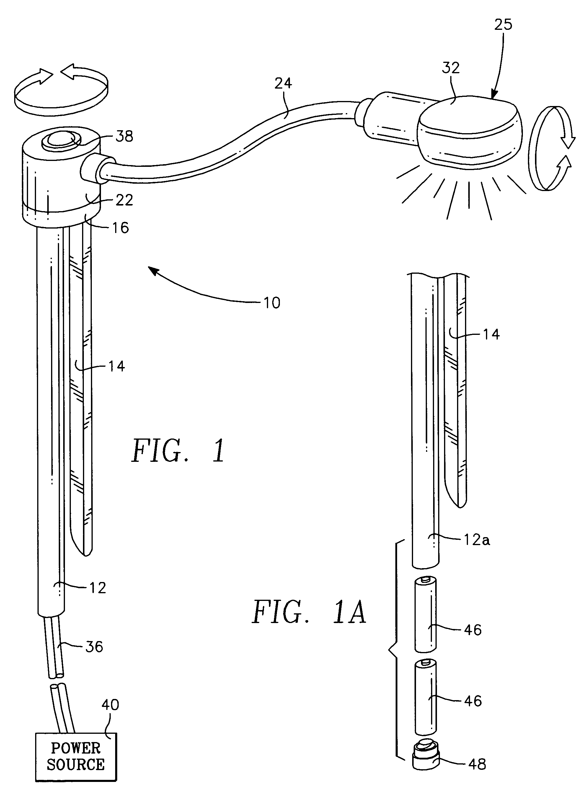
[0018]The present invention, an improved portable book light, comprises a light source coupled to an adjustable support arm, a rotational device, a front gripping member, and a back gripping member and can be powered by a variety of conventional power sources. The front gripping member and the back gripping member are removably mountable to a book spine or book binding at a front side and a backside of the book spine respectively, wherein the front gripping member and the back gripping member are configured to sandwich the book spine. The front gripping member cross-sectional shape is flat and thin for insertion into a crease formed by a right and a left hand page at the front side of the book spine. The front gripping member flat surfaces slide easily and deeply into the page crease and forms a substantially small bulge between the pages so that the book binding is not harmed and the pages lie essentially flat. The rotational device is configured to provide full 360 degree rotation of the light source and support arm about a longitudinal axis of the book spine and mounted gripping members. This configuration enables a reader to comfortably hold and read a paperback book folded back upon itself with one hand, the page facing the reader is well illuminated, and subsequent pages can be illuminated by turning the folded book over to a new page and simply rotating the support arm and light source over the new reading page, all without having to remove and re-mount the book light from the book.
[0019]Furthermore, In the case of paperback books, because the book light gripping members firmly mount to the book spine—making the gripping members and the book spine essentially an integral structure—the book light mounting system can be made substantially more compact and lightweight. Additionally, mounting to the book spine of hardcover and paperback books also positions the light source at the center of the book, thereby providing generally equal illumination to the right and left hand pages of the book held in the open book reading position. Also, because the book spine is generally the most rigid component of the paperback book, mounting to the spine facilitates a stable light thereby significantly reducing light bounce and wobble. Another benefit of the book spine mounted book light is that light drift across the page is held to a minimum for the book being held open at varying angles. These and other objects and advantages of the present invention will become more fully apparent from the following description taken in connection with the accompanying drawings.

Problems solved by technology

However, prior art has selectively addressed these problems and has not provided a solution that encompasses all associated problems.
Moreover, some reader desired features, such as enabling reading in the folded book reading position, have not been specifically addressed in the prior art.
However, the covers, support structure, and attachment mechanisms of these devices are bulky and restrictive do not enable the reader to efficiently fold a paperback book back upon itself for reading in the folded book reading position.
Additionally, because these devices generally cover or enclose the book they are substantially large and heavy and contribute significantly to reader hand and arm fatigue.
However, these book lights have no effective provision for repositioning the light source over each newly turned page of a folded book.
When turning pages while reading in the folded book reading position, these book lights would need to be removed from one cover and clipped back on the opposing cover to illuminate each newly turned page, a highly cumbersome use requirement.
Additionally, because these book lights are designed to attach to a flimsy cover and pages of a paperback book, the clip-on mechanisms are made excessively wide to keep light source wobble and bounce to a minimum.
A further disadvantage of mounting to the cover and pages of a book is that an off-center mounted light source inherently causes unequal illumination of opposing pages in the open book reading position.
Additionally, the off-center mounted light source will drift undesirably across the pages if the reader effects even small changes in the angle in which the book is held open.
However, both these devices, because they mount to both opposing covers of the book, would hold the book in the unfolded reading position and not enable the reader to efficiently fold the book back upon itself.
However, the aforementioned disadvantages of Zeller and Chen for off-center paperback book cover and page mounting would apply.
Additionally, the Langdon and Melamed patents disclose book lights that are substantially bulky and heavy.
However, this gap does not form when a paperback book is opened and therefore the clip attachment cannot be used as disclosed for paperback books.
However, again the aforementioned disadvantages of Zeller and Chen for off-center paperback book cover and page mounting would apply.
However, each of these lighting devices have their own significant disadvantages.
For example, desk lamps and bed post mounted lamps flood a room with too much light and can disturb the reader's partner trying to sleep.
Flashlights need to be held, a highly cumbersome use requirement.
Head and ear mounted lighting devices can become very uncomfortable to wear after even short periods.
And lastly, lamps that are worn around the neck or rest on a person's chest do not work well if a person reads on their back or side.
Hence, the prior art devices are inadequate for meeting the needs of readers as described in the aforementioned reader desired features and operations.
As discussed, prior art devices that meet some of these needs suffer a number of other disadvantages.

Method used


Image

  • Book spine mounted book light
  • Book spine mounted book light
  • Book spine mounted book light

Examples


Embodiment Construction

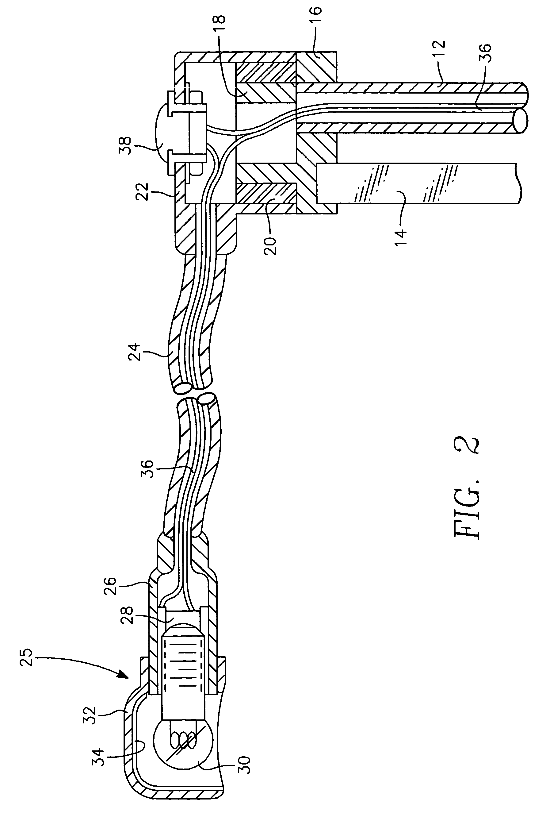
[0050]Reference will now be made to the drawings wherein like numerals refer to like parts throughout. A preferred embodiment of the present invention is illustrated in FIG. 1. Book light 10 comprises a back gripping member 12 and a front gripping member 14 for removably mounting book light 10 to a book spine 44 (FIGS. 3 and 4), an outer rotational bearing 22 that is rotatably or pivotably mounted to inner stationary bearing 18 (FIG. 2) to provide 360 degrees rotation of flexible arm 24 about a longitudinal axis of gripping members 12 and 14. Specifically, front gripping member 14 and back gripping member 12 are removably mountable to book spine 44 at a front side and a backside of book spine 44 respectively (FIGS. 3 and 4), so that front gripping member 14 and back gripping member 12 are configured to elastically sandwich book spine 44. Book light 10 further comprises a lighting assembly, or light source, generally indicated in 25 coupled to flexible arm 24 and powered by a convent...


PUM


Abstract

A book light that is removably mounted to a book spine, has a flexible lamp support arm, and provides a rotational device that enables full 360 degree rotation of the lamp support arm about a longitudinal axis of the book spine such that a reader can comfortably hold and read a paperback book folded back upon itself with one hand, a page facing the reader is well illuminated, and subsequent pages can be illuminated by turning the folded book over to a new page and simply rotating the lamp support arm and lamp over the new reading page, all without having to remove and re-mount the book light from the book.

Description

CROSS-REFERENCE TO RELATED APPLICATIONS[0001]This application claims the benefit of provisional patent application No. 60 / 478,176, filed Jun. 16, 2003 by the present inventors.FEDERALLY SPONSORED RESEARCH[0002]Not ApplicableSEQUENCE LISTING OR PROGRAM[0003]Not ApplicableBACKGROUND OF THE INVENTION[0004]1. Field of Invention[0005]This invention relates to a portable book light and, more particularly, to an improved book light that enables a reader to illuminate pages of a paperback book while the book is folded back upon itself in addition to being removably mountable to a book spine for reading paperback books and hardbound books.[0006]2. Discussion of the Prior Art[0007]In general, portable book lights are usually removably mounted in some manner to a book and provide a reader a light source for night reading that will minimally disturb other persons in the room. Book lights also have the advantage of a light source that is close to the book and adjustable over the pages being read...

Claims


Application Information

Patent Timeline
IPC IPC(8): A47B19/00
CPCB42D3/123F21V33/0048F21V21/32F21W2131/3005
Inventor MAJOR, WILLIAM ROBERTMAJOR, WILLIAM JOSEPH
Owner MAJOR WILLIAM ROBERT
Learn More