Volume rendering of 3D sonar data

a sonar data and volume rendering technology, applied in the field of sonar imaging and control, can solve the problems of sparse and noisy three-dimensional matrix return of sonar ping data, and achieve the effect of improving image quality

Active Publication Date: 2014-10-07
CODA OCTOPUS GROUP
View PDF11 Cites 10 Cited by
  • Summary
  • Abstract
  • Description
  • Claims
  • Application Information

AI Technical Summary

Problems solved by technology

Sonar ping data is typically returned as a very sparse and very noisy three dimensional matrix.

Method used


Image

  • Volume rendering of 3D sonar data
  • Volume rendering of 3D sonar data
  • Volume rendering of 3D sonar data

Examples


Embodiment Construction

[0023]It has long been known that data presented in visual form is much better understood by humans than data presented in the form of tables, charts, text, etc. However, even data presented visually as bar graphs, line graphs, maps, or topographic maps requires experience and training to interpret them. Humans can, however, immediately recognize and understand patterns in visual images which would be impossible for even the best and fastest computers to pick out. Much effort has thus been spent in turning data into images.

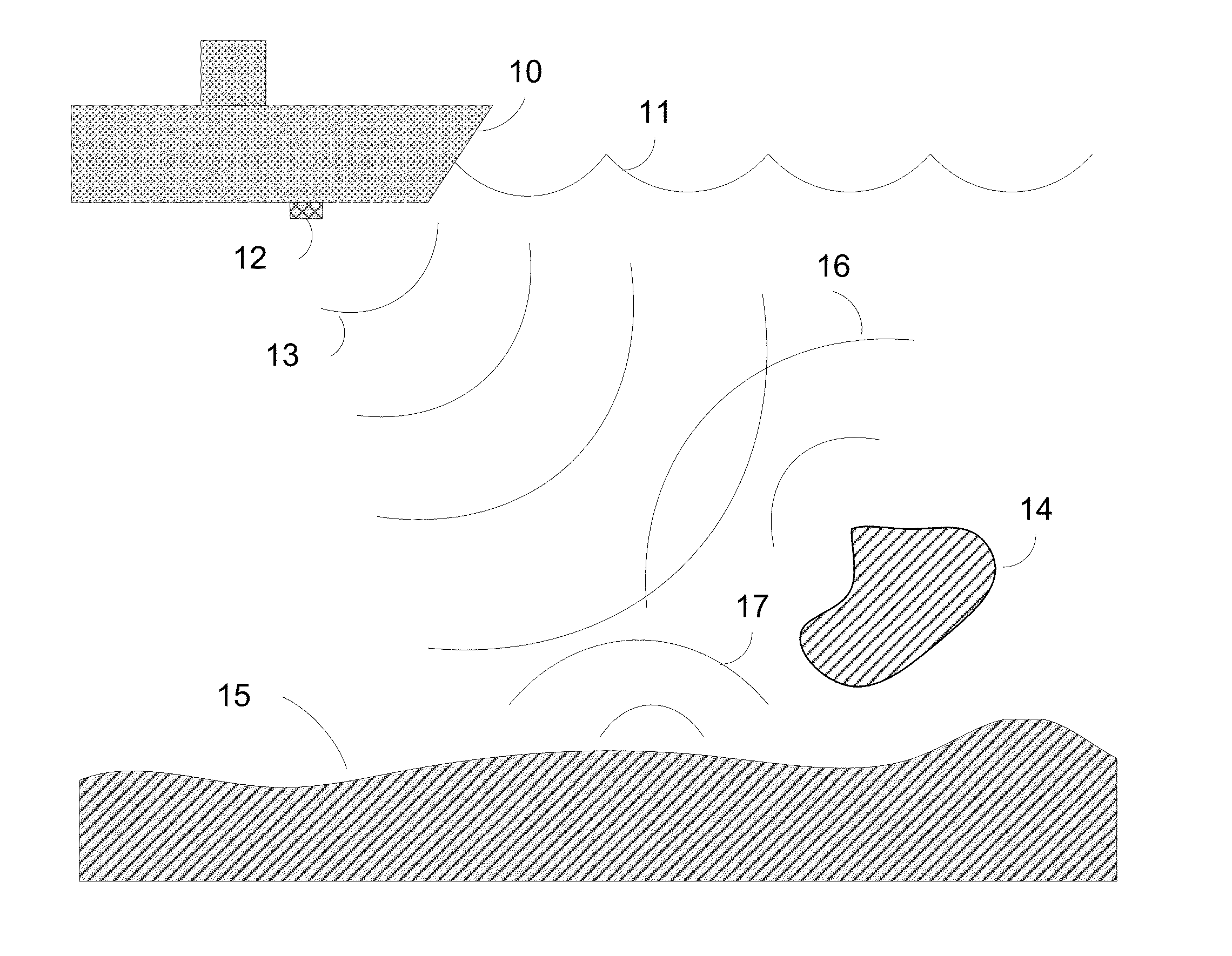
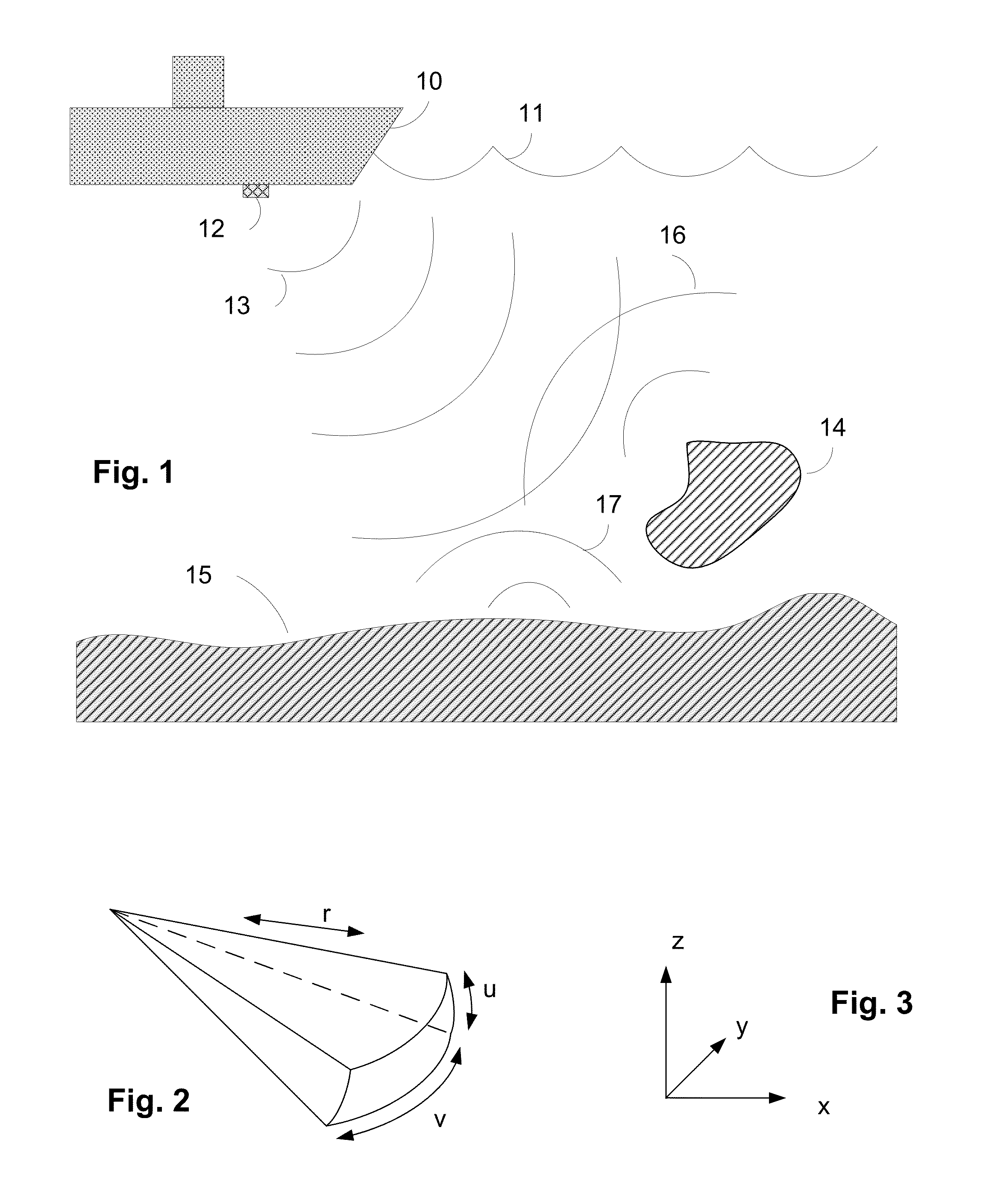
[0024]In particular, images which are generated from data which are not related to light are difficult to produce. One such type of data is sonar data, wherein a sound waves are sent out from a generator into a volume of fluid, and the reflected sound energy from objects in the ensonified volume is recorded by a multielement detector. The term “ensonified volume” is known to one of skill in the art and is defined herein as being a volume of fluid through which sou...


PUM


Abstract

Sonar imaging data obtained by sending multiple sonar pings towards an object is reduced by assigning values measured by each sonar ping to bins, where each bin is fixed in World Space, and calculating the opacity of each bin to produce an image of the object. A normal vector associated with each bin is used to calculate the light reflected from a model constructed from the data. The most preferred normal vector is calculated from the vector sum of normals calculated from each ping.

Description

RELATED PATENTS AND APPLICATIONS[0001]The following US Patents and US patent applications are related to the present application: U.S. Pat. No. 6,438,071 issued to Hansen, et al. on Aug. 20, 2002, and entitled “Method for producing a 3D image”; U.S. Pat. No. 7,466,628 issued to Hansen on Dec. 16, 2008; U.S. Pat. No. 7,489,592 issued Feb. 10, 2009 to Hansen and entitled “Patch test for 3D sonar data”; U.S. Pat. No. 8,059,486 Sloss on Nov. 15, 2011 and entitled “Method of rendering volume representation of sonar images”; U.S. Pat. No. 7,898,902 issued to Sloss on Mar. 1, 2011 and entitled “Method of representation of sonar images”. A U.S. patent application Ser. No. 13 / 603,723 entitled “Object tracking using sonar imaging”, filed on the same day (Sep. 5, 2012) as the present invention by the inventor of the present invention, is also related to the present application[0002]The above identified patents and patent applications are assigned to the assignee of the present invention and ar...

Claims


Application Information

Patent Timeline
Patent Type & Authority Patents(United States)
IPC IPC(8): G01S15/89
CPCG01S15/89G01S7/52003G01S7/6245
Inventor SLOSS, MARTYN
Owner CODA OCTOPUS GROUP
Why Eureka
Try Eureka