Multi-beam sonar high-precision imaging method based on motion compensation

An imaging method and motion compensation technology, applied in the re-radiation of sound waves, radio wave measurement systems, and the use of re-radiation, etc., can solve the problems of affecting imaging quality, sonar signal interference, complex underwater environment, etc., to achieve high imaging accuracy, Accurately correspond to the effect

Active Publication Date: 2021-07-23
HANGZHOU DIANZI UNIV
View PDF8 Cites 3 Cited by
  • Summary
  • Abstract
  • Description
  • Claims
  • Application Information

AI Technical Summary

Problems solved by technology

However, due to the complex underwater environment, sonar signal attenuati...

Method used


Image

  • Multi-beam sonar high-precision imaging method based on motion compensation
  • Multi-beam sonar high-precision imaging method based on motion compensation
  • Multi-beam sonar high-precision imaging method based on motion compensation

Examples


Embodiment Construction

[0053] The present invention is further described below.

[0054] A motion compensation-based multi-beam sonar high-precision imaging method, comprising the following steps:

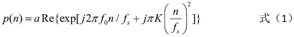
[0055]Step 1: The multi-beam sonar transmits the array element, transmits the chirp signal, and samples the chirp signal. The sampled chirp signal is shown in formula (1):

[0056]

[0057] In formula (1), p(n) is the chirp signal after sampling, a is the amplitude of the transmitted signal, "Re()" represents the real part, and "exp()" is based on the natural constant e=2.71828 exponential function, f 0 is the carrier frequency, f s is the sampling frequency, K is the modulation frequency, n is the time sampling sequence number of the upward distance, n=0,1,2,...,N-1, where N is the total number of sampling points.

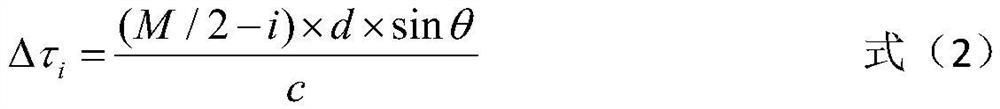
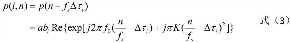
[0058] Step 2: Set the time delay generated by each sub-array element relative to the center point of the receiving array under the far-field condition, taking the center of the rece...


PUM


Abstract

The invention relates to a multi-beam sonar high-precision imaging method based on motion compensation, and aims to overcome the defect of insufficient imaging precision due to factors such as motion errors, limited number of sub-arrays and noise in sonar imaging of an existing beam forming method. The method comprises the following steps of: firstly, performing time delay error compensation on an echo signal by using a motion compensation method in beam forming; after actual echo delay is obtained, carrying out two-dimensional Fourier transform on echo signals, and completing beam forming; performing pulse compression processing with upward distance on the signal after beam forming; carrying out modulus on the compressed signal, performing squaring and then carrying out noise reduction post-processing; and finally, performing interpolation processing on the signal after noise reduction processing in an angle domain, thereby realizing multi-beam sonar high-precision imaging.

Description

technical field [0001] The invention belongs to the field of multi-beam sonar signal processing, in particular to a multi-beam sonar high-precision imaging method using motion compensation. Background technique [0002] Multi-beam sonar refers to a sonar that simultaneously forms multiple beams within a certain spatial range. Since multiple beams work at the same time, information of multiple channels can be obtained, so multiple targets in different directions can be observed and tracked at the same time, and it is not easy to lose contact. [0003] Beamforming is the core technology of multi-beam sonar. The principle of its algorithm is to form a matrix with elements according to a specific geometric shape, and make the matrix form a beam with a direction at a desired angle. The directional beam formed by the matrix means that the position of the object can be accurately determined. If multiple directional beams are formed within the predetermined direction range, the ide...

Claims


Application Information

Patent Timeline
IPC IPC(8): G01S15/89
CPCG01S15/89
Inventor 易志强郭飞宏张福洪曾嵘
Owner HANGZHOU DIANZI UNIV
Why Eureka
Try Eureka