Multi-orthogonal emission front-view sonar

A pre-launch, sonar technology, applied to radio wave measurement systems, instruments, etc., can solve problems such as multiple receiving channels, high cost, and complex equipment

Inactive Publication Date: 2017-08-11
NAVAL UNIV OF ENG PLA
View PDF6 Cites 3 Cited by
  • Summary
  • Abstract
  • Description
  • Claims
  • Application Information

AI Technical Summary

Problems solved by technology

But there are also many receiving channels (the international advanced forward-looking sonar has about 200 channels); the equipment is complicated and the cost is high.

Method used


Image

  • Multi-orthogonal emission front-view sonar
  • Multi-orthogonal emission front-view sonar
  • Multi-orthogonal emission front-view sonar

Examples


Embodiment 1

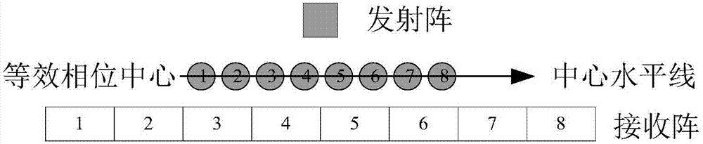
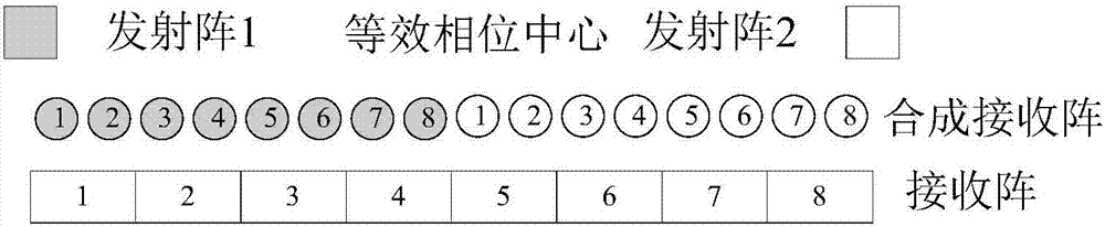
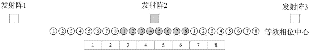
[0023] This implementation example is 8 receiving array elements, three orthogonal transmitting forward-looking sonar

[0024] Its transceiver array, equivalent phase center and composite receiving array are as follows: image 3 As shown, the number of elements of the composite receiving array is 24, the aperture of the phase center is three times that of the single transmitting array, and the resolution is three times that of the single transmitting array.

[0025] Assume that the interval between receiving array elements is d, along the direction of the central horizontal line, which is the positive direction of coordinates, and the equivalent phase centers are uniformly distributed: the interval between adjacent transmitting arrays is 8·d, and the maximum interval between three emitting arrays is 16·d. The phase central aperture is three times that of a single transmitter, and the length of the three-orthogonal transmitter array is approximately twice that of a receiver arr...

Embodiment 2

[0028] In this embodiment, there are N array elements and M orthogonal transmitting array forward-looking sonars

[0029] The number of elements of the synthetic receiving array is M·N, the aperture of the phase center is M times that of the single-emitting array, and the resolution is M times that of the single-emitting array.

[0030] Assume that the interval between receiving array elements is d, so that the law of uniform distribution of the phase center space is (1) the interval between two adjacent transmitting arrays is N d, (2) the maximum interval between transmitting arrays is M-1 times the length of the receiving array, that is (M-1) N d.

[0031] In the direction of the central horizontal line, if it is desired that the horizontal symmetry axis of the equivalent phase center coincides with the horizontal symmetry axis of the receiving array, the horizontal symmetry axis of the transmitting array should also coincide with the symmetry axis of the receiving array. T...


PUM


Abstract

The invention relates to a multi-orthogonal emission front-view sonar. The front-view sonar employs two or more emission arrays having different phase centers, mutual orthogonal signals are emitted, M orthogonal emission signals are synthesized, and a reception array aperture is M times as large as a single emission array aperture. The front-view sonar is advantaged in that on the condition that the array dimension is fixed, the front-view sonar imaging resolution can be effectively improved, on the condition that the resolution is fixed, the reception array dimension and a channel number can be reduced, and system complexity is reduced.

Description

technical field [0001] The invention belongs to a forward-looking sonar, in particular to a multi-orthogonal emission forward-looking sonar, which is used for improving the resolution of the forward-looking sonar, or reducing the number of receiving channels and system complexity. Background technique [0002] Forward-looking sonar is a commonly used image sonar, which is mainly used for mine hunting and side-scan sonar for blindness compensation and collision avoidance. Such as figure 1 As shown, it generally consists of a single transmitting array that transmits to a wide beam in azimuth and a multi-element receiving array (the number of array elements in the schematic diagram is 8), and the beamforming method is used to form multiple receiving beams with very narrow beam widths. The forward-looking sonar has the advantages of high resolution (the azimuth beam width is as low as 0.5 degrees), and the advantages of surveying and mapping scene images can be obtained with a ...

Claims


Application Information

Patent Timeline
Patent Type & Authority Applications(China)
IPC IPC(8): G01S7/524G01S7/526
CPCG01S7/524G01S7/526
Inventor 唐劲松吴浩然钟何平田振丘昌镇张森徐魁
Owner NAVAL UNIV OF ENG PLA
Why Eureka
Try Eureka