
Power generator

a power generator and power supply technology, applied in the direction of motors, dynamo-electric components, dynamo-electric machines, etc., can solve the problems of increasing environmental demands, increasing power consumption every day, and increasing environmental pollution, and achieve high efficiency and stable electricity

Inactive Publication Date: 2014-10-28
JUN DONG POWER
View PDF8 Cites 4 Cited by
  • Summary
  • Abstract
  • Description
  • Claims
  • Application Information

AI Technical Summary

Benefits of technology

[0009]It is therefore an objective of the present invention to have a power generator providing stable electricity with high efficiency.
[0016]Thus, a heavy gyro body is used to provide a stable mechanical energy, and then the mechanical energy is transmitted to an electricity generation device through a transmission disk and a rotation disk. All approaches in the energy transmission employ rotary movement of machineries, and thereby the energy loss during the energy transmission may decrease. In addition, the rollers are gathered in small groups on the transmission disk to form a larger pitch for the inclined grooves of the rotation disk such that the rotation disk of the electricity generation module can still be meshed with or separated from the transmission disk easily even when the transmission disk is still rotating.

Problems solved by technology

However, power consumption is increasing every day.
Therefore, the environmental demands are increasing and environmental pollution is getting worse.
Currently, there are pros and cons for nuclear power usage; its further development, in particular, has caused a long-term debate.
As to waterpower, most of the water resources have been utilized and the impact of waterpower to nature is always criticized; its future is also very limited.
In addition, the environmental pollution and greenhouse effect due to burning coals are not yet solved, either.

Method used


Image

  • Power generator
  • Power generator
  • Power generator

Examples


Embodiment Construction

[0025]Reference will now be made in detail to the present preferred embodiments of the invention, examples of which are illustrated in the accompanying drawings. Wherever possible, the same reference numbers are used in the drawings and the description to refer to the same or like parts.

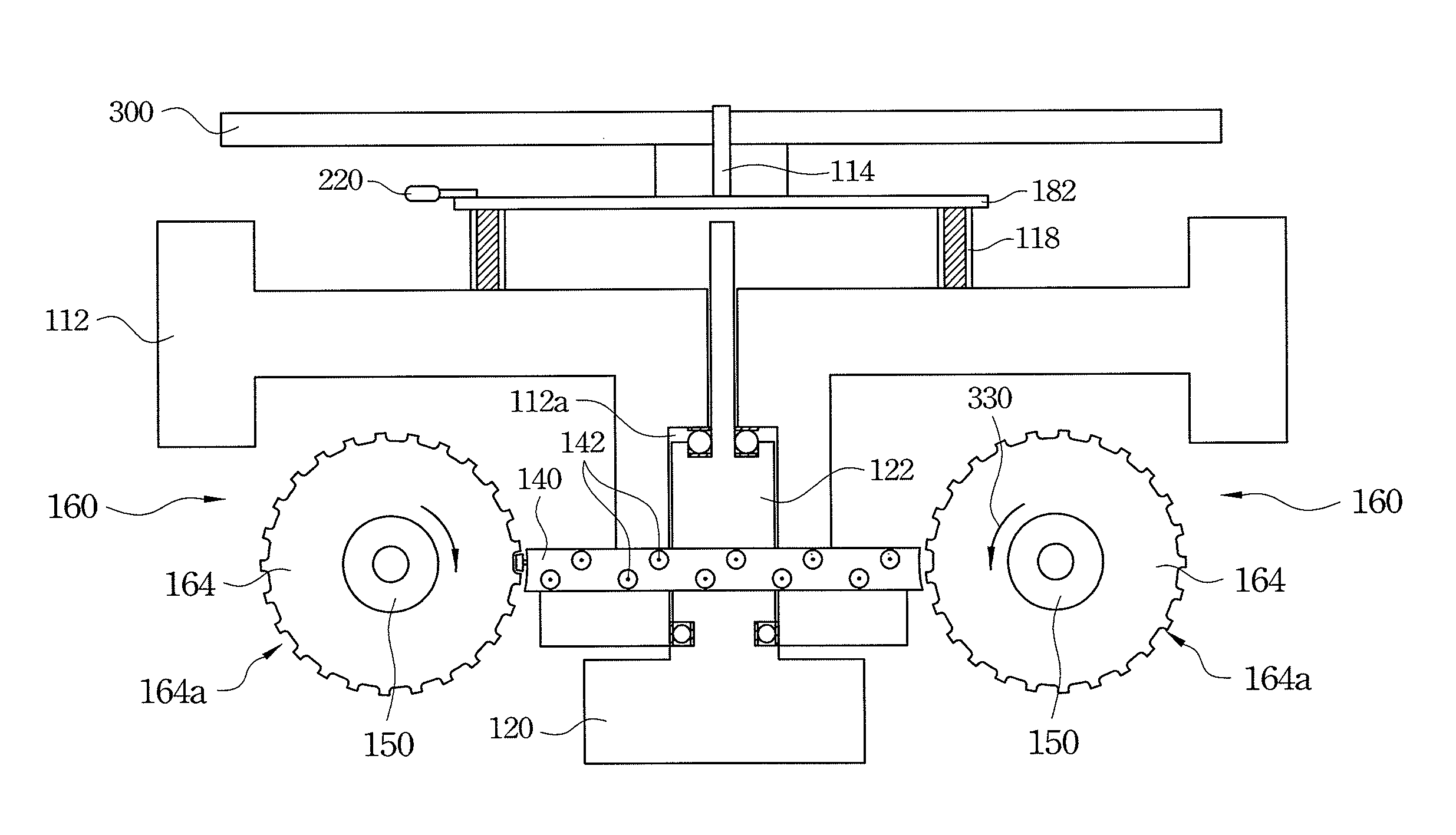
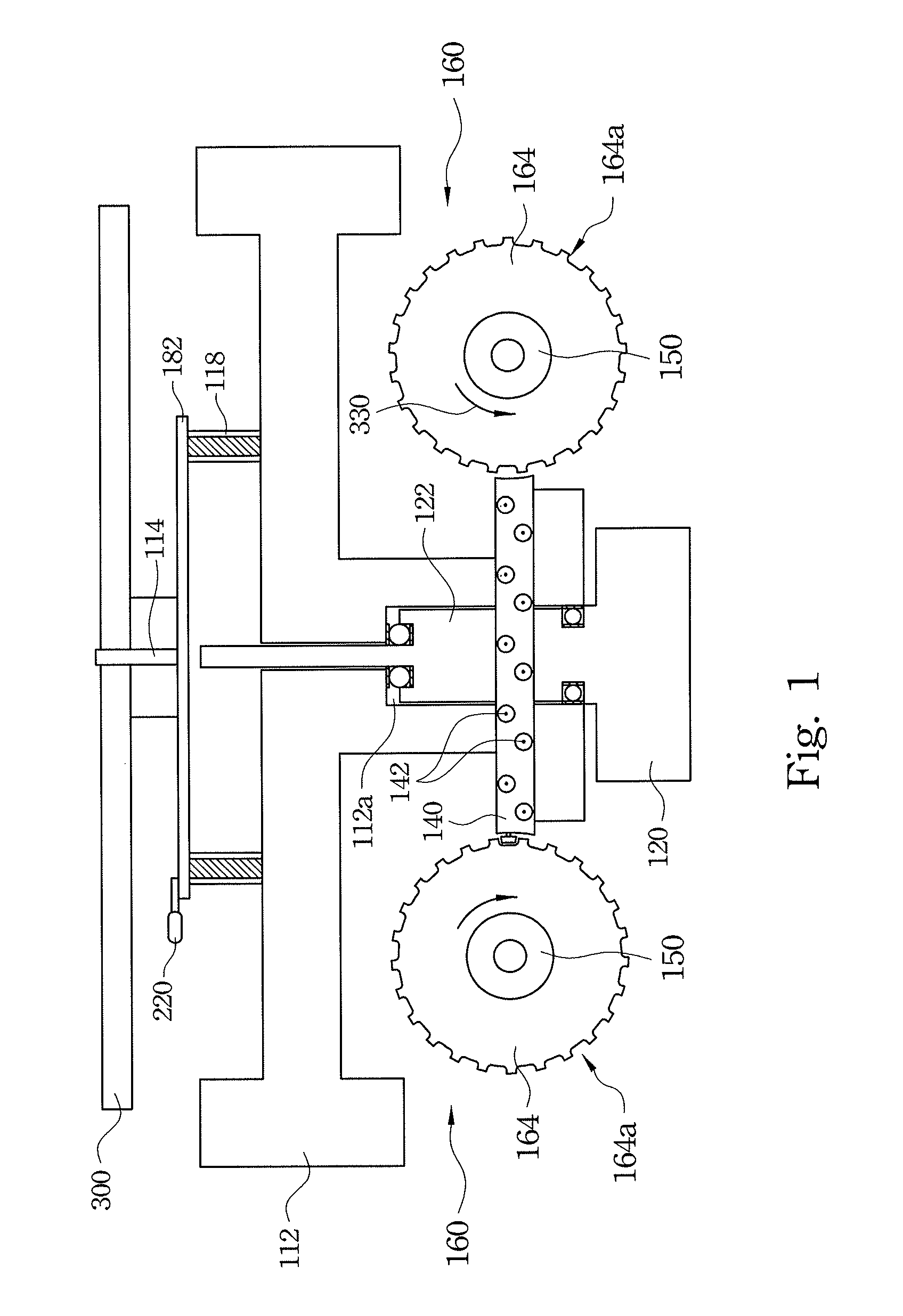
[0026]FIG. 1 illustrates a schematic cross-sectional view of a power generator according to one preferred embodiment of this invention. As illustrated in FIG. 1, the power generator includes a heavy gyro body 112, a driving device 200, a transmission disk 140 and a rotation disk 164.

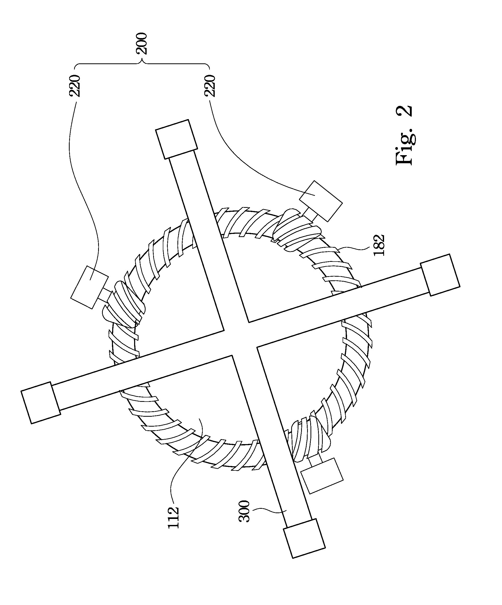
[0027]The heavy gyro body 112 includes a gear ring 182 on its top surface, and the gear ring 182 is symmetrically arranged relative to the spindle 114. The gear ring 182 is secured to the heavy gyro body 112 by a connection ring 118. The spindle 114 penetrates the heavy gyro body 112 and serves as a central axis of the heavy gyro body 112. The spindle 114 is a vertical spindle, that is, the spindle 114 is perpendicular to...


PUM


Abstract

A power generator includes a heavy gyro body, a driving device, a transmission disk and an electricity generation module. The driving device is used to drive the heavy gyro body to rotate about a vertical spindle. The transmission disk is secured to and rotatable simultaneously with the heavy gyro body. The transmission disk has a plurality of rollers at a sidewall thereof. The electricity generation module has a rotation disk, which has a plurality of inclined grooves at a sidewall thereof. Each inclined groove is meshed with a corresponding roller of the transmission disk such that the transmission disk is able to drive the rotation disk to rotate, wherein an included angle between an inner sidewall of each inclined groove and a horizontal plane is more than 0 degree and less than 45 degrees.

Description

RELATED APPLICATIONS[0001]This application claims priority to Taiwan Application Serial Number 101115212, filed Apr. 27, 2012, which is herein incorporated by reference.BACKGROUND[0002]1. Field of Invention[0003]The present disclosure relates to a power generator. More particularly, the present disclosure relates to a power generator with a heavy gyro body.[0004]2. Description of Related Art[0005]With the rapid growth in commercial / industrial activities and comfortable living needs in recent years there is a higher demand and dependency on electric power. Currently, electric power is generated mainly from nuclear power, coal, oil, gas, wind, ground heat, and solar energy.[0006]The energy resources on the Earth are continuously exhausted. However, power consumption is increasing every day. Therefore, the environmental demands are increasing and environmental pollution is getting worse. In view of the limited energy resources on the Earth, it is imperative for scientists to find new s...

Claims


Application Information

Patent Timeline
Patent Type & Authority Patents(United States)
IPC IPC(8): H02K7/18
CPCY02E10/725F03G3/08Y02E10/72
Inventor TSAI, MING-CHUN
Owner JUN DONG POWER
Learn More