
Low coherence interferometric system for phase stepping shearography combined with 3D profilometry

a technology of interferometry and phase stepping shearography, which is applied in the field of low coherence interferometry for phase stepping shearography combined with 3d profilometry, can solve the problems of compromising fringe stability, complex electromechanical or optoelectronic systems, and inability to ensure repeatability and robustness

Inactive Publication Date: 2014-10-28
COCKERILL MAINTENANCE & INGIE +1
View PDF4 Cites 3 Cited by
  • Summary
  • Abstract
  • Description
  • Claims
  • Application Information

AI Technical Summary

Benefits of technology

[0040]a translation device for precisely displacing said two-way interferometer from said first location to said second location and vice versa, comprising a rail that is curved on one of its ends, having a “J” shape, so that the precision displacement of the interferometer corresponds to a combination of a strict geometric translation with a rotation of an angle which does not exceed 45°.

Problems solved by technology

The problem of contrast is especially critical when ambient light cannot be shut down, for instance in outdoor in-situ conditions.
However, dynamically shifting or scaling interferometric projection pattern often requires precise and complex electromechanical or optoelectronic systems whose repeatability and robustness is not assured.
Internal vibrations are also a possible cause of trouble that compromises fringe stability.
Despite these good results, this installation does not meet industrial needs such as robustness and fastness.
Prior art methods for detecting depth defects are unsatisfactory:in the case of coated rolls, use of a transparent polyurethane layer for visual control is not always desired by the client;ultrasound control time is lengthy and unacceptable for the industry (30-40 minutes per roll);sound emitted by a roll after an external stimulus is empirical and unreliable.

Method used


Image

  • Low coherence interferometric system for phase stepping shearography combined with 3D profilometry
  • Low coherence interferometric system for phase stepping shearography combined with 3D profilometry
  • Low coherence interferometric system for phase stepping shearography combined with 3D profilometry

Examples


Embodiment Construction

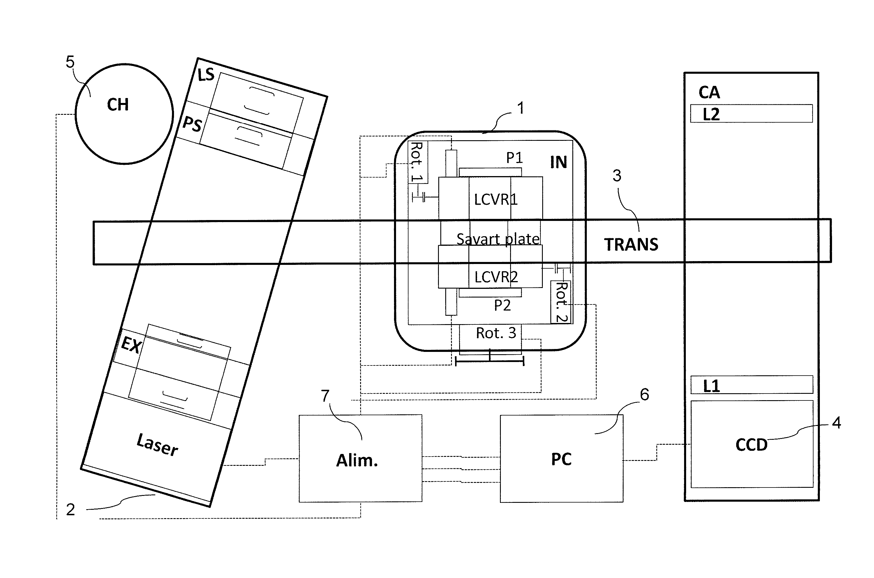
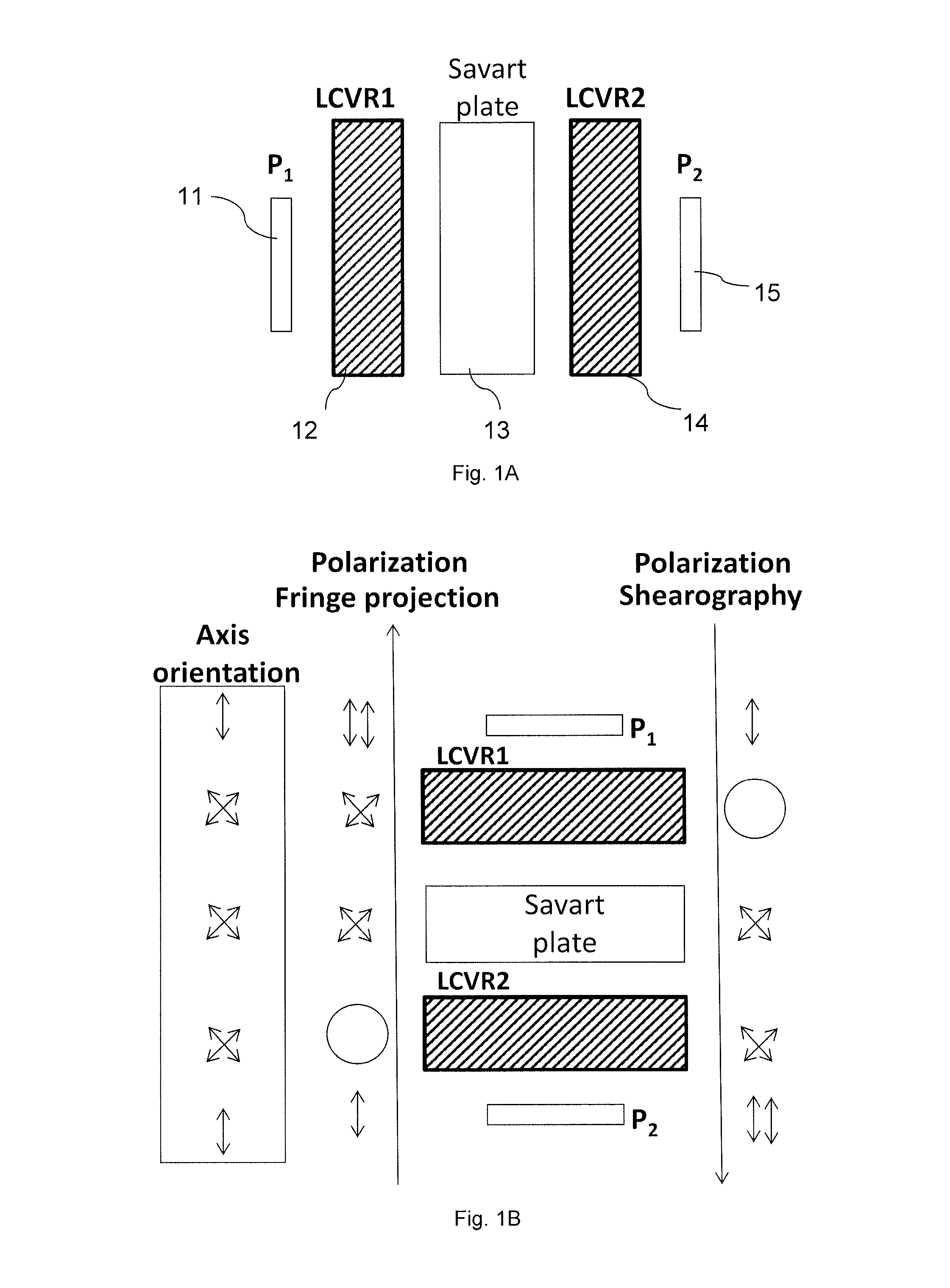
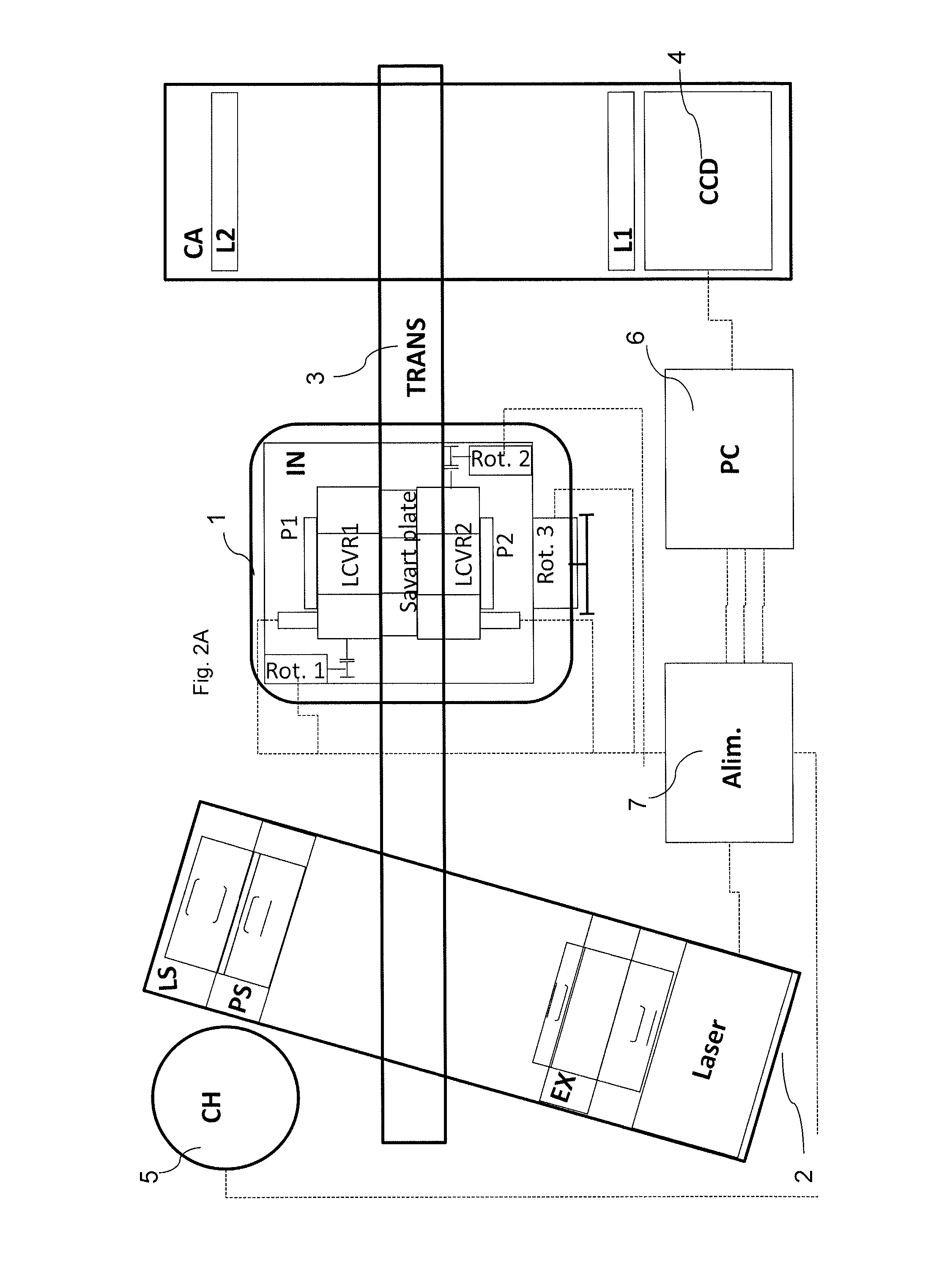
[0075]The apparatus of the present invention comprises an interferometer, which performs as a multipurpose metrological device.

[0076]On the one hand, this interferometer can be set in front of a CCD camera to constitute an optical measurement system which is a shearography interferometer. The latter allows measuring micro displacements between two states of the studied object under coherent or quasi-coherent lighting.

[0077]On the other hand, by producing and shifting multiple sinusoidal Young's interference patterns with this interferometer, and using a CCD camera, it is possible to build a 3D structured-light profilometer. In this configuration the same interferometer as above is used this time together with the laser lighting system to project fringes. This method, known as moiré method, usually comprises projecting a periodic light pattern that can be the result of the interference of two coherent beams, forming a deformed line pattern on said object, and synthesizing the 3D shap...


PUM


Abstract

The present invention relates to a portable industrial instrument for performing, in an integrated and two-way manner, an interferometric fringe projection and shearography, on a object to be tested, so that, when the two-way interferometer (1) is associated with the coherent or quasi-coherent projection device (2), the instrument is able to measure the 3D shape of the object by interferometric fringe projection, also known as moiré method, and, when the two-way interferometer (1) is associated with the recording or imaging device (4), the instrument is able to perform shearographic measurements on the object, the direction of the traversing light beam in the interferometer (1) being reversed when shifting from one measurement configuration to the other one.

Description

CROSS-REFERENCE TO RELATED PATENT APPLICATIONS[0001]This patent application claims priority to European Application No. 11191890.0, filed Dec. 5, 2011, the entire teachings and disclosure of which are incorporated herein by reference thereto.FIELD OF THE INVENTION[0002]The present invention relates to a method for measuring the three-dimensional shape (or 3D shape) of an object by means of interferometric fringe projection or moiré method and detecting structural defects within the object by means of shearography, in particular phase stepping shearography.[0003]The invention also relates to an apparatus for carrying out the method.BACKGROUND OF THE INVENTION AND PRIOR ARTFringe Projection Methods (or Moiré Methods)[0004]A number of non-contact optical measurement methods have been developed in the recent years and applied in many industrial and research domains. Some devices take for example advantage of the polarization states splitting technique for producing and shifting multiple...

Claims


Application Information

Patent Timeline
Patent Type & Authority Patents(United States)
IPC IPC(8): G01B11/25G01B9/02G01B11/16
CPCG01B9/02095G01B11/162G01B9/0203G01B11/2527G01B9/02098G01B2290/70
Inventor BLAIN, PASCALRENOTTE, YVONHABRAKEN, SERGEWAROUX, PASCAL
Owner COCKERILL MAINTENANCE & INGIE
Learn More