

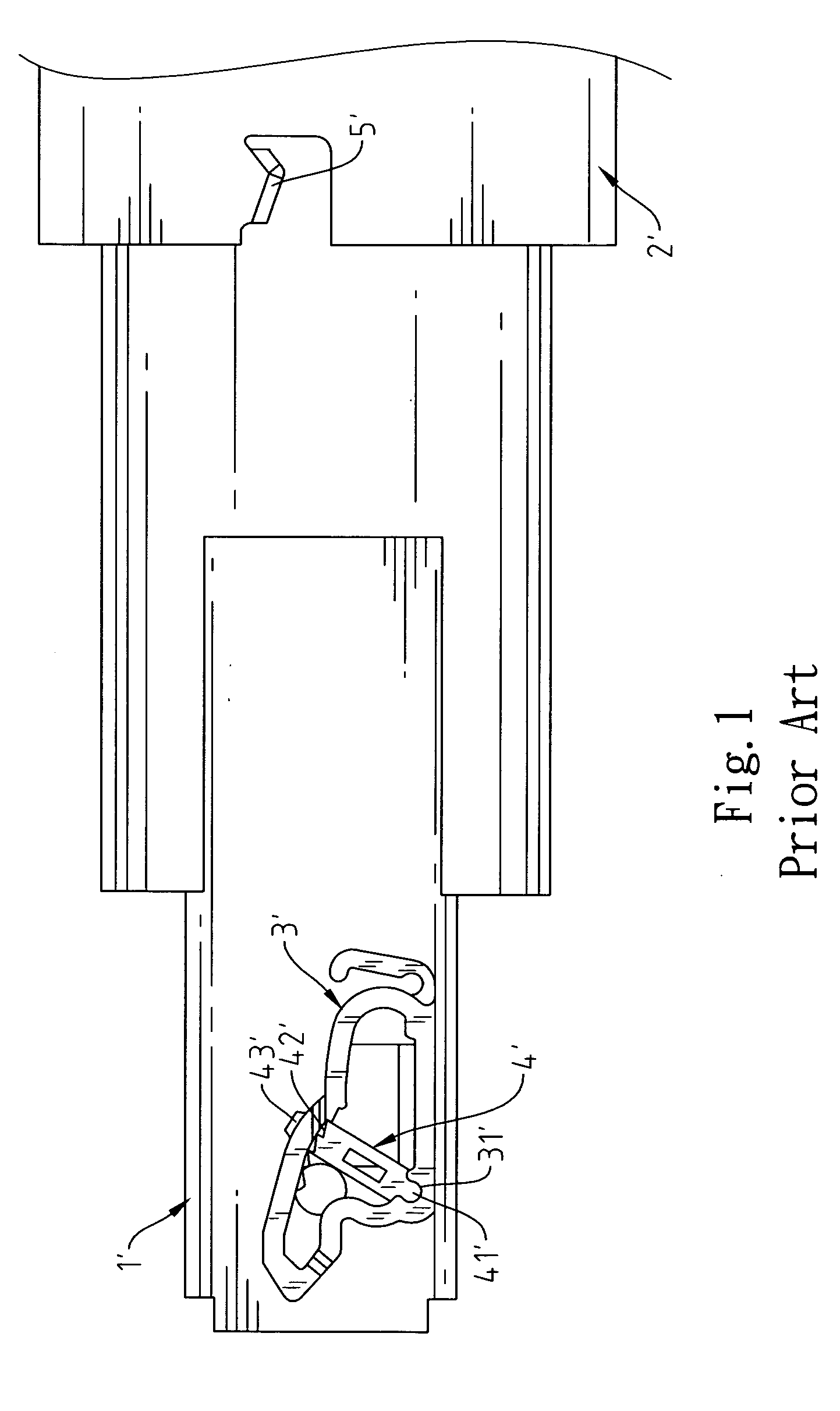
Structure of pull adjustable catch for drawer slide
a technology of adjustable catch and drawer slide, which is applied in the direction of ball bearings, furniture parts, domestic applications, etc., can solve the problems of inconvenient general operators, requiring special tools and strength,
- Summary
- Abstract
- Description
- Claims
- Application Information
AI Technical Summary
Benefits of technology
Problems solved by technology
Method used
Image


Examples
Embodiment Construction
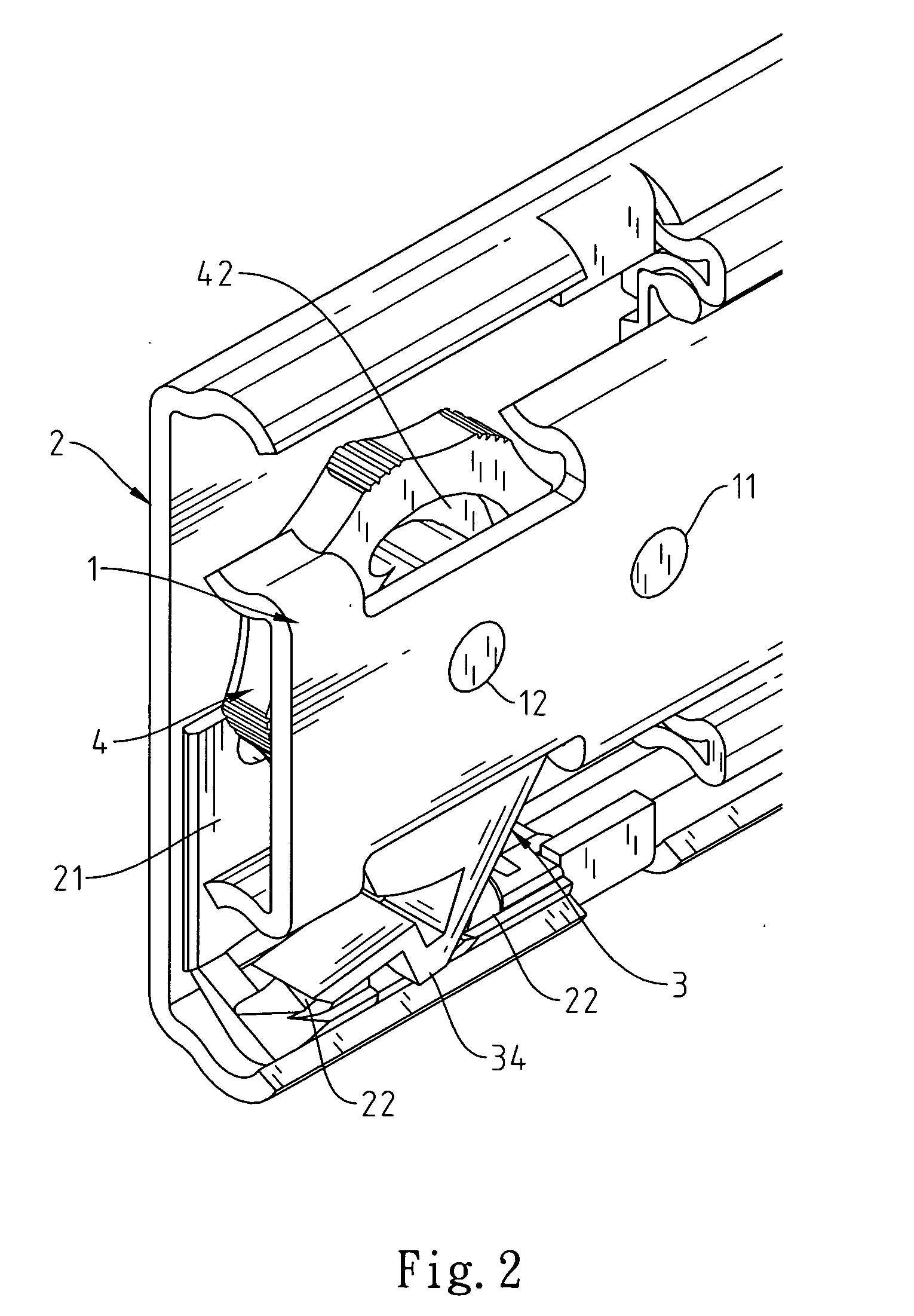
[0013] As shown in FIGS. 2 through 4, the structure of the adjustable catch for the drawer slide mainly comprises an adjustable catch 3 outfitted at the front end of slide track 1 and a turning knob 4.
[0014] The adjustable catch 3 has a lock hole 31 at one end to be fastened by means of a rivet to the first lock hole 11 of the slide track 1 allowing the adjustable catch 3 to swing along the slide track 1. On the center part of the adjustable catch 3, there provides a curved flange 32 and a retaining stud 33 and a retaining spring 34 at the bottom end of the adjustable catch 3.
[0015] The center of turning knob 4 has a lock hole 41 to be fixed to the second lock hole 12 on the slide track 1 with a rivet. The turning knob 4 has a dented curved guide groove 42 with a curvature exactly corresponding to the curved flange 32 of catch 3, and fitting the retaining stud 33 of catch 3 to move within the grove.
[0016] There is a bumper 21 mounted on the front end of the outer slide panel 2 Th...
PUM
 Abstract
Description
Claims
Application Information