Method and apparatus for correcting thermal displacement of machine tool

a technology of machine tools and thermal displacement, which is applied in the direction of computer control, program control, instruments, etc., can solve the problems of thermal displacement at the machine tool having the spindle, adversely affecting the machining accuracy of the machine tool, and producing friction heat from the rolling bearing

Active Publication Date: 2007-07-17
YAMAZAKI MAZAK KK
View PDF9 Cites 22 Cited by
  • Summary
  • Abstract
  • Description
  • Claims
  • Application Information

AI Technical Summary

Benefits of technology

[0007]Accordingly, it is an objective of the present invention to provide a method and an apparatus for correcting thermal displacement of a machine tool that require no complicated processes when a spindle rotation speed, which is used for computing thermal displacement, changes, and eliminate the necessity for separately measuring heat generation and heat radiation.
[0008]It is another objective of the present invention to provide a method and an apparatus for correcting thermal displacement of a machine tool that properly predict thermal displacement even if a spindle rotation speed changes, and, as a result, is capable of appropriately correcting thermal displacement.

Problems solved by technology

Such rolling bearings produce friction heat.
Heat generated by heat sources of machine tool parts causes thermal displacement at the machine tool having the spindle.
Thermal displacement of a machine tool adversely affects machining accuracy of the machine tool.
However, immediately after the spindle rotation speed changes, the changed time constant of the thermal displacement does not match with the change time constant of the measured temperature.
Thus, the thermal displacement cannot be easily corrected in an appropriate manner.
Also, when the spindle rotation speed changes as described above, particularly complicated processes need to be executed.
Therefore, the estimation of thermal displacement by separately obtaining heat generation and heat radiation is difficult and not practical.

Method used


Image

  • Method and apparatus for correcting thermal displacement of machine tool
  • Method and apparatus for correcting thermal displacement of machine tool
  • Method and apparatus for correcting thermal displacement of machine tool

Examples


first embodiment

[0046]At step S40, the CPU 110 performs a data averaging procedure. Specifically, the CPU 110 computes the mean value of values of the rotation speed of the spindle 14, which have been consecutively sampled at step S10. The CPU 110 uses the mean value of the rotation speed of the spindle 14 in a correction expression at step S50. The mean value of the rotation speed of the spindle 14 is represented by ω. The mean value of the rotation speed of the spindle 14 is computed as an arithmetic average in the

(Step S50)

[0047]At step S50, the CPU 110 computes a correction amount using the correction expression. In the first embodiment, the following equation is used as the correction expression.

Sn=b1·Sn−1+b2·ω+b3·ω2+b4·ω3+b5·Sn−1·ω  (3)

[0048]Using the expression (3), the correction amount of the thermal displacement amount of the spindle 14, that is, a thermal displacement amount Sn of the current execution of the program is computed. The computed thermal displacement amount Sn will hereafter...

second embodiment

[0111]The characteristics of the second embodiment will now be described.

[0112]FIG. 9 is a diagram in which the displacement (actual displacement−correction amount) of the spindle 14 along the Z-axis direction in a third comparison example (g), a fourth comparison example (o), and a fifth example (m) are plotted in a case where the rotation speed of the spindle motor 350, that is, the rotation speed of the spindle 14 is repeatedly changed in the pattern shown in FIG. 8. The pattern of FIG. 8 is repeated with a cycle of 13.2 seconds. Specifically, increase and decrease of the rotation speed of the spindle 14 are repeated approximately every six seconds between the stopped state of the spindle 14 and a high rotation speed state of ten thousand rotations per minute. The repetition pattern is started at about twenty minutes of elapsed time on the time axis in FIG. 9, and is ended at two and half hours of elapsed time so that the rotation speed of the spindle 14 becomes zero.

[0113]The pa...

third embodiment

[0115]A third embodiment according to the present invention will now be described with reference to FIG. 10. The third embodiment is different from the first embodiment in that steps S10B, step S40B, and step S50B are executed instead of steps S10, S40, and S50 in the flowchart of the thermal displacement correction.

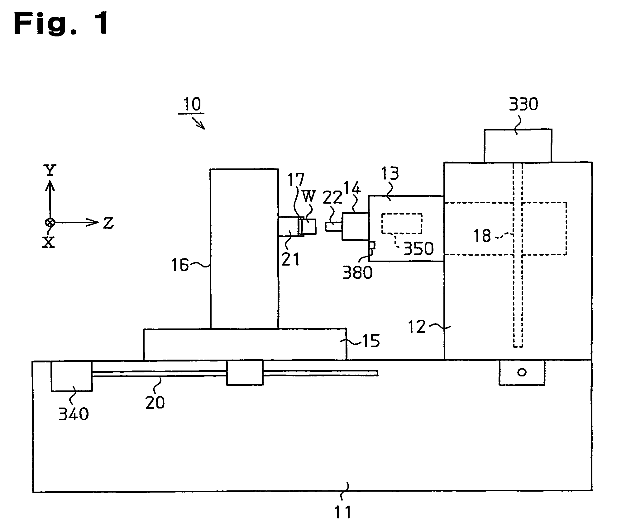
[0116]At step S10B, the CPU 110 samples the rotation speed of the spindle 14 based on a rotation pulse signal from the rotation speed sensor 370 for the spindle 14. Further, the CPU 110 samples the load on the spindle 14 based on a current detection signal from the current sensor 360. Also, the CPU 110 samples the temperature (measured value) of the spindle 14 based on a temperature detection signal from the temperature sensor 380. The spindle temperature sensor 380 corresponds to a detection section of the temperature of the spindle 14.

[0117]At step S40B, the CPU 110 performs a data averaging procedure. Specifically, the CPU 110 computes the mean value of the rotation s...


PUM


Abstract

A method corrects thermal displacement of a machine tool having a rotational spindle. The method includes detecting a rotation speed of the spindle. A thermal displacement amount of the spindle in the current cycle of execution of a program is estimated by using an arithmetic expression that is based at least on the spindle rotation speed and a thermal displacement amount that has been estimated in the preceding cycle of execution of the program. The estimated thermal displacement amount in the current cycle is used as a correction amount for canceling the thermal displacement of the spindle. Therefore, thermal displacement of a machine tool is corrected with no complicated processes when a spindle rotation speed changes.

Description

BACKGROUND OF THE INVENTION[0001]The present invention relates to a method and an apparatus for correcting thermal displacement of a machine tool. Specifically, the present invention relates to a method and an apparatus for correcting thermal displacement of a machine tool caused by heat generated by rotation of a spindle.[0002]In general, parts of a machine tool can be heat sources. Heat sources include rolling bearings of a spindle. Such rolling bearings produce friction heat. Heat generated by heat sources of machine tool parts causes thermal displacement at the machine tool having the spindle. Thermal displacement of a machine tool adversely affects machining accuracy of the machine tool. Accordingly, various types of methods and apparatus for correcting thermal displacement have been conventionally proposed.[0003]Japanese Patent No. 3151655 discloses a method for correcting thermal displacement that is performed on the precondition that thermal displacement is proportionate to ...

Claims


Application Information

Patent Timeline
Patent Type & Authority Patents(United States)
IPC IPC(8): G06F19/00B23Q15/18G05B19/404G05B19/4155
CPCG05B19/404G05B2219/49204G05B2219/49214G05B2219/49219
Inventor SUZUKI, YASUHIKOTANAHASHI, MAKOTO
Owner YAMAZAKI MAZAK KK
Why Eureka
Try Eureka