Integrated vehicle fluids

a technology of vehicle fluids and integrated fluids, which is applied in the direction of vessels, instruments, explosions, etc., can solve the problems of increased pressure within the vehicle tank, difficult to improve upon, and complex cryogenic regulators, etc., and achieves the reduction of peak pressure, increased temperature, and decreased pressure

Active Publication Date: 2014-11-11
UNITED LAUNCH ALLIANCE
View PDF29 Cites 7 Cited by
  • Summary
  • Abstract
  • Description
  • Claims
  • Application Information

AI Technical Summary

Benefits of technology

[0024]The selection of a Wankel engine provides some advantages as compared to a traditional piston engine; however, either the piston engine or Wankel engine is contemplated for use in the present invention. As compared to a piston engine, a Wankel engine has no intake or exhaust valves, has fewer moving and lubricated parts, a very simple crank system, and is a very dynamically balanced engine due to its symmetrical disposition with respect to the movement of the rotor. Because of this simplicity the engine is very light. The three chamber configuration of the rotary engine has distinct hot and cold areas that can enable very simple gas cooling, yet may achieve higher exhaust gas temperatures that can be used as the exhaust gas for the settling thrusters. Regardless of the type of engine used, because of the limitations on combustion physics and materials, the engine preferably operates at a very low mixture ratio between 0.6 and 2. This range precisely matches the boil off characteristics of the vehicle which often generates more H2 than O2. Hence the engine more effectively uses the waste gases from the vehicle.
[0050]Another function is sustained vehicle settling to drastically reduce propellant losses in the upper stage propellant tanks.

Problems solved by technology

Unspoken but also implicit is that commercially viable launchers must fill this broad range of demands since single-purpose launchers such as the Saturn rocket or Space Shuttle are cost prohibitive, even for governments with substantial space budgets.
Each individual system on the launchers has been raised to a high level of performance which is very difficult to improve upon, even with large investments in engineering development.
These vent valves are thus precision cryogenic regulators that are complex, costly and heavy.
However, during the ascent phase of flight and also prior to operation of the upper stage engines, the pressures within the vehicle tanks must be raised.
Without system pressure maintained above saturation pressure, the propellants would boil within the pumps and they would cease to function properly.
However even the most advanced existing systems have strict limitations on their capabilities.
These systems all have a limited amount of GHe and hence the number of engine burns, tank size, and other factors are all limited.
Even a small leak of helium from the storage systems can result in a catastrophic loss of pressurant and hence mission failure.
Therefore, tank designs may have to account for much higher pressures, such as a 60 psia capability, which results in a substantial mass penalty.
A significant limiting factor for all missions in space is accounting for the ullage losses associated with the continual boil off of cryogens.
Heat is conducted down the side walls from the warm ullage side of the tank to the cold liquid side but this is inhibited by the relatively long conductive distances, reduced thermal conductivity due to the cryogenic operating temperatures and low wall thicknesses.
Naturally, the amount of time that a hydrazine system can support settling is strictly limited by the amount of propellant that it contains.
While the settling function consumes the vast majority of hydrazine capacity, the attitude control task cannot be ignored.
Even if settling is eliminated, the attitude control function alone can consume hundreds of pounds of propellant over the course of a multiday mission.
Regarding the use of hydrazine as a propellant, while its application to space vehicles is widespread, there are a number of problems associated with its use.
Hydrazine is a highly toxic, highly corrosive fluid that is compatible with only a handful of materials.
Handling hydrazine requires hazardous procedure precautions, often requiring the use of positive-internal pressure inflatable SCAPE (Self Contained Atmospheric Protective Ensemble) suits to protect technicians loading a vehicle.
Hence, elaborate thermal control measures including heaters are mandatory, thus burdening the electrical storage system and exacerbating propellant heating.
Hydrazine is also quite costly.
Hydrazine is also a very inefficient fuel, delivering only a miserly specific impulse of 235 seconds.
Nevertheless, the continued use of hydrazine sets harsh boundaries on improving overall vehicle operations and costs.
Even with the best modern technology, these batteries are extremely heavy, costly and can only supply enough power for less than a day's operation of a vehicle such as a Centaur®.
Without a means to recharge these batteries, they set a strict limit on mission duration.
Unfortunately the two common sources of power for recharge are solar panels and fuel cells, and these systems are both very costly to incorporate on a vehicle.
Use of solar panels requires vehicle orientation control relative to the sun, and are physically bulky with complex deployment mechanisms.
A vehicle like Centaur® will generate acceleration forces in excess of 2 G's, and hence the mounting system for even a small solar array would be very heavy.
Fuel cells, while being more compact than batteries efficient and seemingly simple, are quite costly and complex to operate and support due to their intolerance of inert gases within the reactant streams and due to the necessity to dispose of the water they produce.
To date, only manned vehicles such as the space shuttle can justify their cost and complexity.
However if the vehicle could efficiently fly for longer, it would be extremely valuable.
The increasing amount of space junk in orbit will soon require the deliberate disposal of not only obsolete satellites but also the stages which placed them in orbit.
This disposal activity at present would impose large performance penalties which would drastically increase the cost to orbit.
While it may be possible to redesign vehicle systems on a micro level, that is, to redesign selected systems based on specific mission requirements, this design approach inevitably compromises the majority of missions and can also create a proliferation of system designs that are all slightly different and likely incompatible.

Method used


Image

  • Integrated vehicle fluids
  • Integrated vehicle fluids
  • Integrated vehicle fluids

Examples


Embodiment Construction

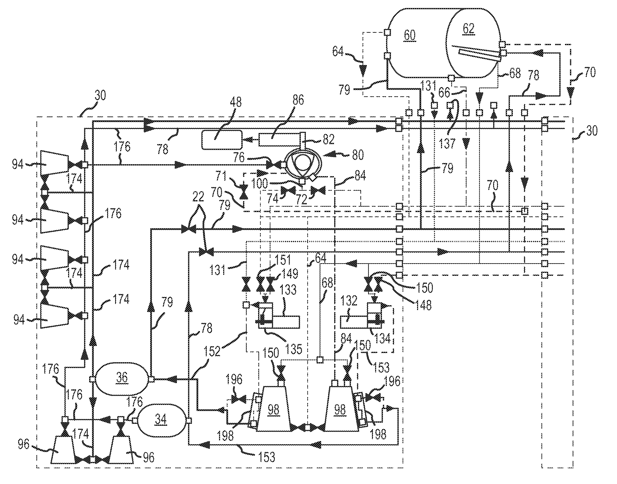
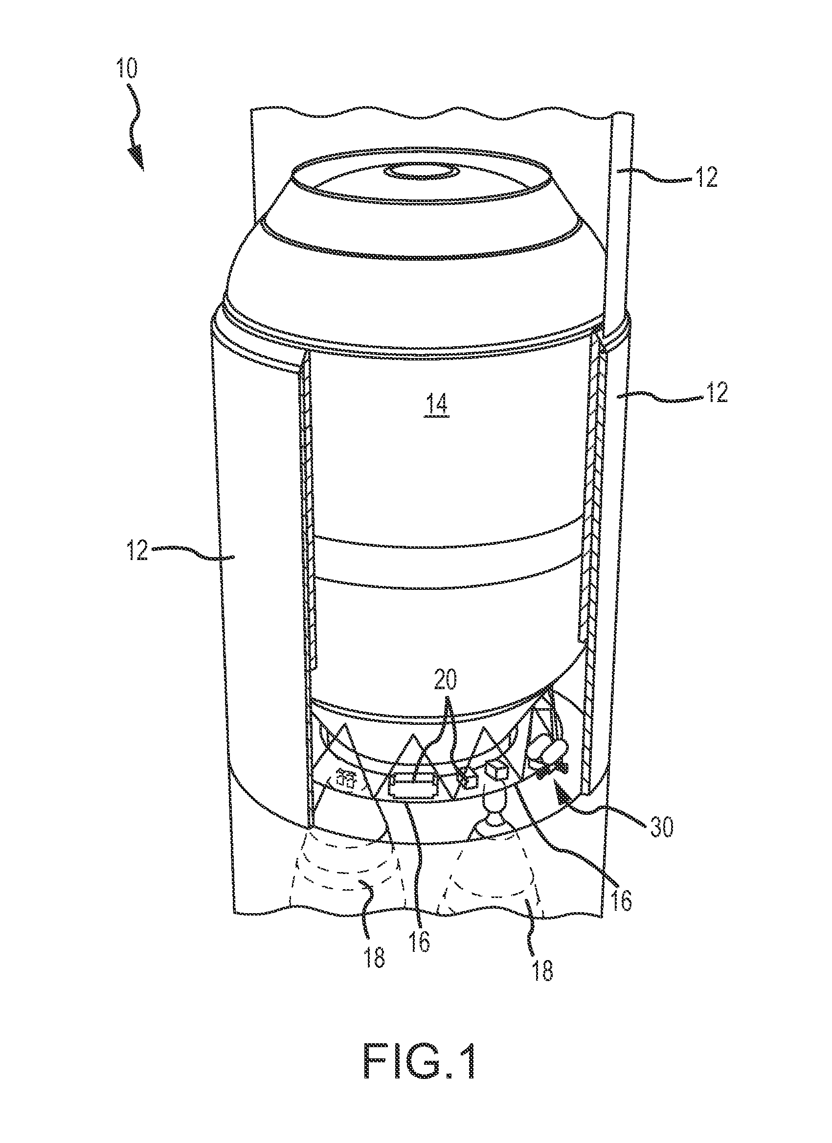
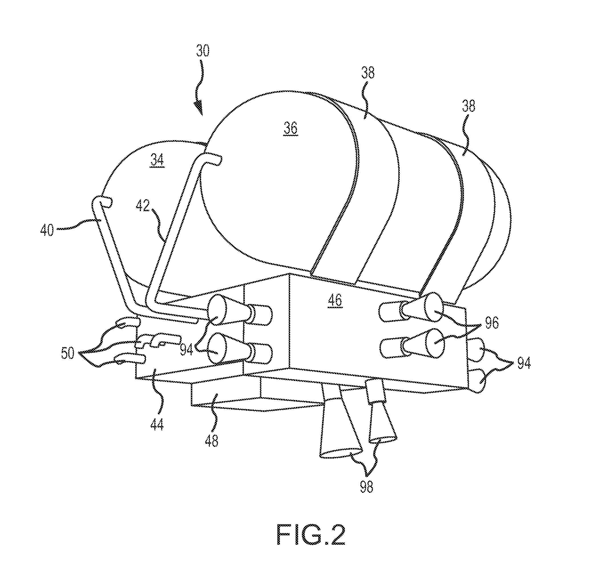
[0072]FIG. 1 illustrates the upper stage 10 of a space launch vehicle. The outer covering or shell 12 is broken away to view the propellant tanks 14, which comprise the liquid hydrogen tank 60 and the liquid oxygen tank 62 with a common bulkhead separating the tanks. The aft of the vehicle includes a circumferential deck 16 that provides for mounting of various system components 20 such as avionics, fluid and mechanical devices as well as the IVF module 30 of the present invention. FIG. 1 also illustrates the main propulsion rockets 18 that are used to propel the upper stage 10. In the Figure, the relatively small size of the IVF module 30 is shown. Preferably, there is an IVF module mounted on opposite sides of the aft deck 16. Twin IVF modules are able to generate more than enough power to supply all of the upper stage system requirements, yet reduce overall vehicle weight by eliminating much of the wiring harness mass associated with traditional vehicles that use battery power. T...


PUM


Abstract

A system and methods are provided for combining systems of an upper stage space launch vehicle for enhancing the operation of the space vehicle. Hydrogen and oxygen already on board as propellant for the upper stage rockets is also used for other upper stage functions to include propellant tank pressurization, attitude control, vehicle settling, and electrical requirements. Specifically, gases from the propellant tanks, instead of being dumped overboard, are used as fuel and oxidizer to power an internal combustion engine that produces mechanical power for driving other elements including a starter / generator for generation of electrical current, mechanical power for fluid pumps, and other uses. The exhaust gas from the internal combustion engine is also used directly in one or more vehicle settling thrusters. Accumulators which store the waste ullage gases are pressurized and provide pressurization control for the propellant tanks. The system is constructed in a modular configuration in which two redundant integrated fluid modules may be mounted to the vehicle, each of the modules capable of supporting the upper stage functions.

Description

FIELD OF THE INVENTION[0001]The invention generally relates to rocket propulsion systems for space launch vehicles placed and maintained in planetary orbits. More specifically, the invention relates to systems and methods for propelling and powering an upper stage of a space launch vehicle by capturing waste ullage gases vented from the main upper stage propellant tanks, and generating power by an internal combustion engine used for replacement of power, pressurization, and reaction control systems traditionally powered by separate hydrazine systems and batteries.BACKGROUND OF THE INVENTION[0002]Over the past decade there have been increasing demands to lower the cost of space transport to geostationary and other orbits as well as perform missions which are simply not possible with existing launchers such as manned exploration of the moon and Mars. Implicit is the demand that reliability be enhanced and certainly not degraded. Unspoken but also implicit is that commercially viable l...

Claims


Application Information

Patent Timeline
Patent Type & Authority Patents(United States)
IPC IPC(8): F42B15/01B64G1/42F42B10/66F02K9/44F42B15/00F02K9/60
CPCF02K9/44B64G1/26B64G1/002B64G1/401B64G1/402B64G1/421B64G1/425
Inventor ZEGLAR, FRANK, C.
Owner UNITED LAUNCH ALLIANCE
Why Eureka
Try Eureka