Aircraft galley chiller system

a chiller system and galley chiller technology, which is applied in the direction of compression machines with several condensers, light and heating equipment, transportation and packaging, etc., can solve the problems of increasing the load on the aircraft cooling system, and inefficiency in the context of the aircraft's overall cooling system, so as to reduce the requirements of other cooling systems

Active Publication Date: 2005-03-24
HAMILTON SUNDSTRAND CORP
View PDF20 Cites 56 Cited by
  • Summary
  • Abstract
  • Description
  • Claims
  • Application Information

AI Technical Summary

Benefits of technology

[0007] This invention provides a galley chiller system for an aircraft that includes at least one condenser having a refrigerant fluid. The fluid within the condenser rejects heat to a first surrounding environment. To more efficiently use the condenser of the galley chiller system and reduce the requirements on other cooling systems within an aircraft, the condenser may reject its heat to a power electronics cooling system. Heat from the condenser may be used to heat a cargo area, or may simply be rejected to ram air of an air conditioning pack of the aircraft cooling system or the exhaust air vent.
[0008] The galley chiller system also includes at least one evaporator that receives fluid from the condenser. In the embodiment shown, the inventive galley chiller system includes at least two evaporators. A first evaporator absorbs heat from a galley which may include a bank of carts. A second evaporator may absorb heat from a cabin upper recirculation air duct of the aircraft cooling system. In this manner, the evaporators of the inventive galley chilling system cool not only the galley carts but also provides supplemental cooling to the aircraft cooling system thereby reducing its cooling requirements.
[0009] The cooling systems of the aircraft may also share some controls to monitor and coordinate the operation of the cooling systems with one another. For example, a controller may be connected to a control valve of the recirculation evaporator to obtain a desirable proportion of refrigerant fluid through the evaporators to adjust the cooling capacity provided to each of the galley carts and upper recirculation air duct. Remotely located heat exchangers may be connected to the condenser and arranged throughout the aircraft enabling the condenser to be packaged compactly with the other galley chiller components while still providing heat to other aircraft areas.
[0010] Accordingly, this invention provides a more efficient galley chiller system that more effectively uses the condenser and evaporator reducing the requirements on the other cooling systems of the aircraft resulting in a reduction in weight and power penalty to the aircraft.

Problems solved by technology

Each of these systems have a significant weight and power penalty associated to the aircraft.
The location of the galley chiller system condenser is such that typically a portion of the heat from the condenser is rejected to the cabin area, which increases the load on the aircraft cooling system.
When the galleys are cooled within the desired temperature range, the galley chiller system may be unused or not operated to its full cooling capacity resulting in inefficiency in the context of aircraft's overall cooling systems.
Therefore, what is needed is a more efficient galley chiller system that more effectively uses the condenser and evaporator to reduce the requirements on the other cooling systems of the aircraft resulting in a reduction in weight and power penalty to the aircraft.

Method used


Image

  • Aircraft galley chiller system
  • Aircraft galley chiller system
  • Aircraft galley chiller system

Examples


Embodiment Construction

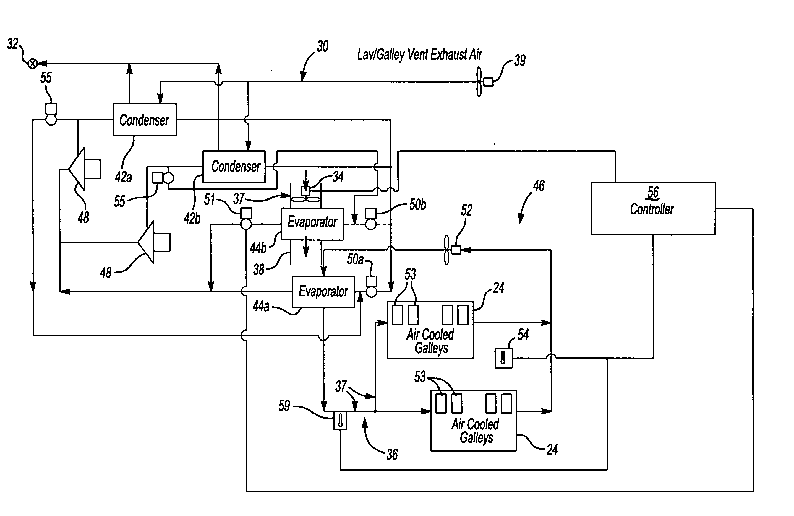
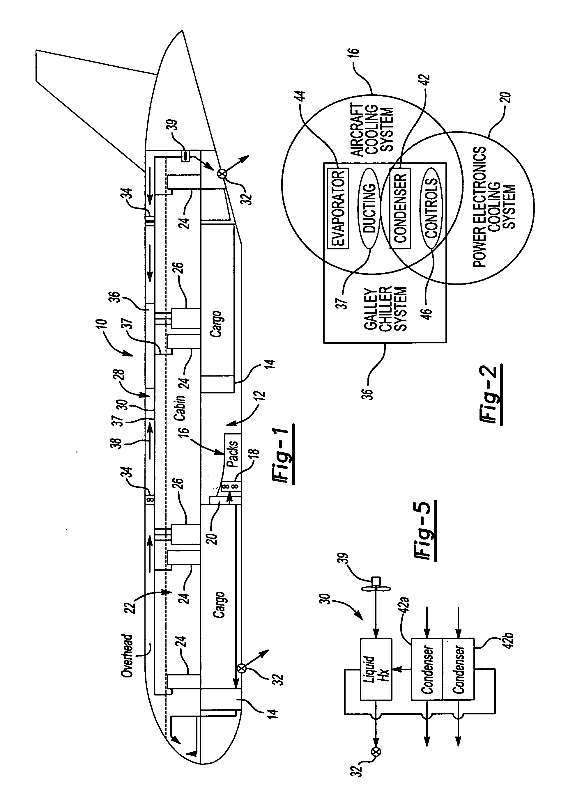
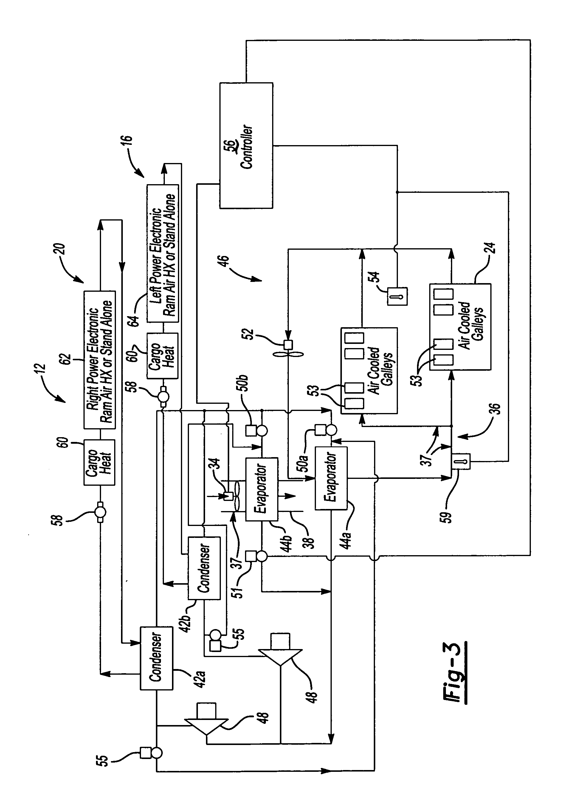
[0017] A high level schematic cross-sectional view of a commercial aircraft 10 is shown in FIG. 1. The aircraft 10 includes a cargo area 12 within the lower portion of the aircraft 10. The cargo area 12 may include one or more power electronics power bays 14 housing various electronic components used in the control and operation of the aircraft 10. An aircraft cooling system 16 includes one or more air conditioning packs typically located within the cargo area 12. The aircraft cooling system 16 provides temperature conditioned air to a cabin area 22 to provide a comfortable climate for the passengers within the cabin area 22. A power electronics cooling system 20 may also be located within the cargo area 12 to cool the power electronics equipment bay 14.

[0018] Galleys 24 are positioned in various convenient locations within the cabin area 22. The galleys 24 house multiple galley carts containing food and other perishable goods. The galleys 24 typically include ducting that delivers...


PUM


Abstract

A galley chiller system for an aircraft includes at least one condenser having a refrigerant fluid. The fluid within the condenser rejects heat to a first surrounding environment. To more efficiently use the condenser of the galley chiller system and reduce the requirement on other cooling systems within an aircraft, the condenser may reject its heat to a desired location using a heat exchanger. The galley chiller system includes at least one evaporator that receives fluid from the condenser. A first evaporator absorbs heat from a galley, which may include a bank of carts. The first evaporator is arranged in ducting that carries cooled air to the carts. A second evaporator may absorb heat from a cabin recirculation air duct of the aircraft cooling system. In this manner, the evaporators of the inventive galley chilling system cools not only the galley carts but also provides supplemental cooling to the aircraft cooling system thereby reducing its cooling requirements.

Description

[0001] The present invention claims priority to U.S. Provisional Patent Application Ser. No. 60 / 504,951 filed Sep. 22, 2003.BACKGROUND OF THE INVENTION [0002] The present invention relates to a galley chiller system for use in an aircraft, and more particularly, the invention relates to a more efficient galley chiller system having components shared with other cooling systems of the aircraft. [0003] A typical commercial aircraft includes at least several nonintegrated cooling systems. For example, an aircraft cooling system primarily provides cooling for the aircraft cabin area. A power electronics cooling system cools the power electronics of various aircraft systems to maintain the electronics within a desired temperature range. A galley chiller system is dedicated to refrigerating the food carts in the galleys located throughout the aircraft. Each of these systems have a significant weight and power penalty associated to the aircraft. It is desirable to minimize the overall weigh...

Claims


Application Information

Patent Timeline
Patent Type & Authority Applications(United States)
IPC IPC(8): B64D11/04B64D13/06F25B1/10F25B5/02F25B6/02F25B41/04F25B47/02
CPCB64D11/04Y10S62/05B64D2013/0614B64D2013/0629F25B1/10F25B5/02F25B6/02F25B41/043F25B47/022F25B2339/047F25B2400/075F25B2600/112F25B2600/2511F25B2700/21173Y02T50/44Y02T50/46B64D13/06Y02T50/40F25B41/22
Inventor ZYWIAK, THOMASBRUNO, LOUIS J.DREW, DIANECHRISTIANS, DOUGLAS L.
Owner HAMILTON SUNDSTRAND CORP
Why Eureka
Try Eureka