Non-to-minimally fractionalized biomass-fueled renewable energy

a renewable energy and non-to-minimally fractional technology, applied in the field of thermodynamics, can solve the problems of particular flaws and flawed bioenergy production, and achieve the effect of facilitating bioenergy applications

Inactive Publication Date: 2014-11-18
JULIAN MARVIN DUANE
View PDF7 Cites 6 Cited by
  • Summary
  • Abstract
  • Description
  • Claims
  • Application Information

AI Technical Summary

Benefits of technology

[0036]Principally, the present Invention provides for the simpler, more practical, and economically viable conversion of Biomass to useful Bioenergy by extraction of its energy content and through its use as a renewable fuel source in its Non-To-Minimally Fractionalized form; whereby no chipping, grinding, etc . . . and / or subsequent recompression (wood pellets) are required. Thus, the present Invention vastly eliminates further well known problematic, higher cost processing, and additional redundant handling and storage of the Biomass prior to its utilization as a renewable fuel. The present Invention provides resolutions to the long-standing and unsolved problems of obtaining useful and renewable energy from colossal volumes of underutilized and / or wasted Non-To-Minimally Fractionalized Biomass by providing useful, real-world, and economically viable solutions. Others have failed to come up with such solutions previously; such failures by others is well documented by the historical and continuing immense waste and underutilization of such Biomass, i.e. open burning, land filling, etc . . . .

Problems solved by technology

Others have failed to come up with such solutions previously; such failures by others is well documented by the historical and continuing immense waste and underutilization of such Biomass, i.e. open burning, land filling, etc .
. . must be undertaken to produce precise and useful Bioenergy is flawed.
Such flaws are particularly revealed in larger scale applications of Biomass-Fuel power generation; especially where “Wood Chip Boilers” and the like are deployed for producing the necessary steam as required by traditional steam turbine generators.

Method used


Image

  • Non-to-minimally fractionalized biomass-fueled renewable energy
  • Non-to-minimally fractionalized biomass-fueled renewable energy
  • Non-to-minimally fractionalized biomass-fueled renewable energy

Examples


Embodiment Construction

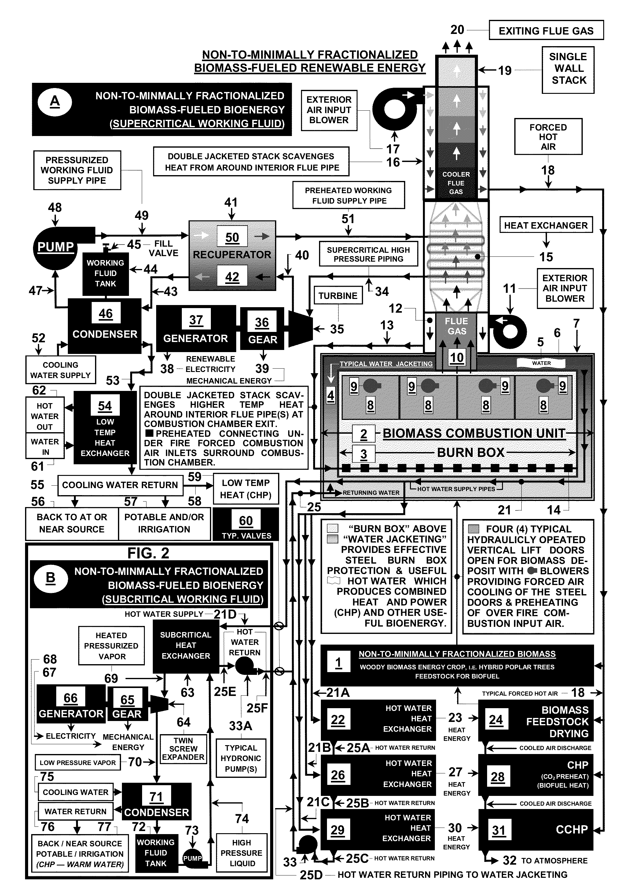
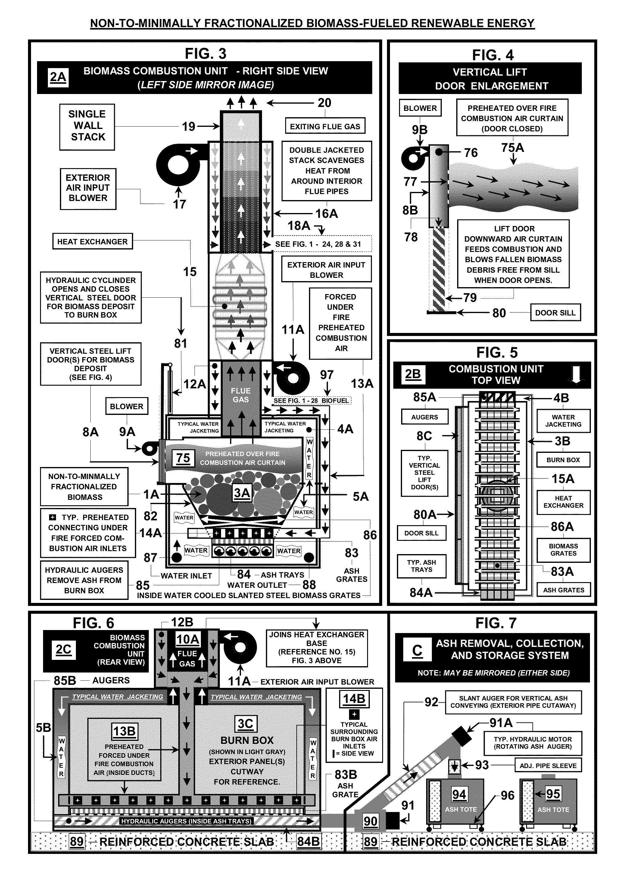
[0064]With reference to FIG. 1 and FIG. 2, a schematic diagram is presented showing systems A and B for “Non-To-Minimally Fractionalized Biomass-Fueled Renewable Energy” provided via thermal communication with Supercritical and Subcritical Working Fluids, respectively. Such renewable energy (Bioenergy) specifically includes: (i) Power Generation, (ii) Heating Applications, (iii) Cogeneration or Combined Heat and Power (CHIP), (iv) Trigeneration or Combined Cooling, Heat, and Power (CCHP), and (v) Mechanical Energy.

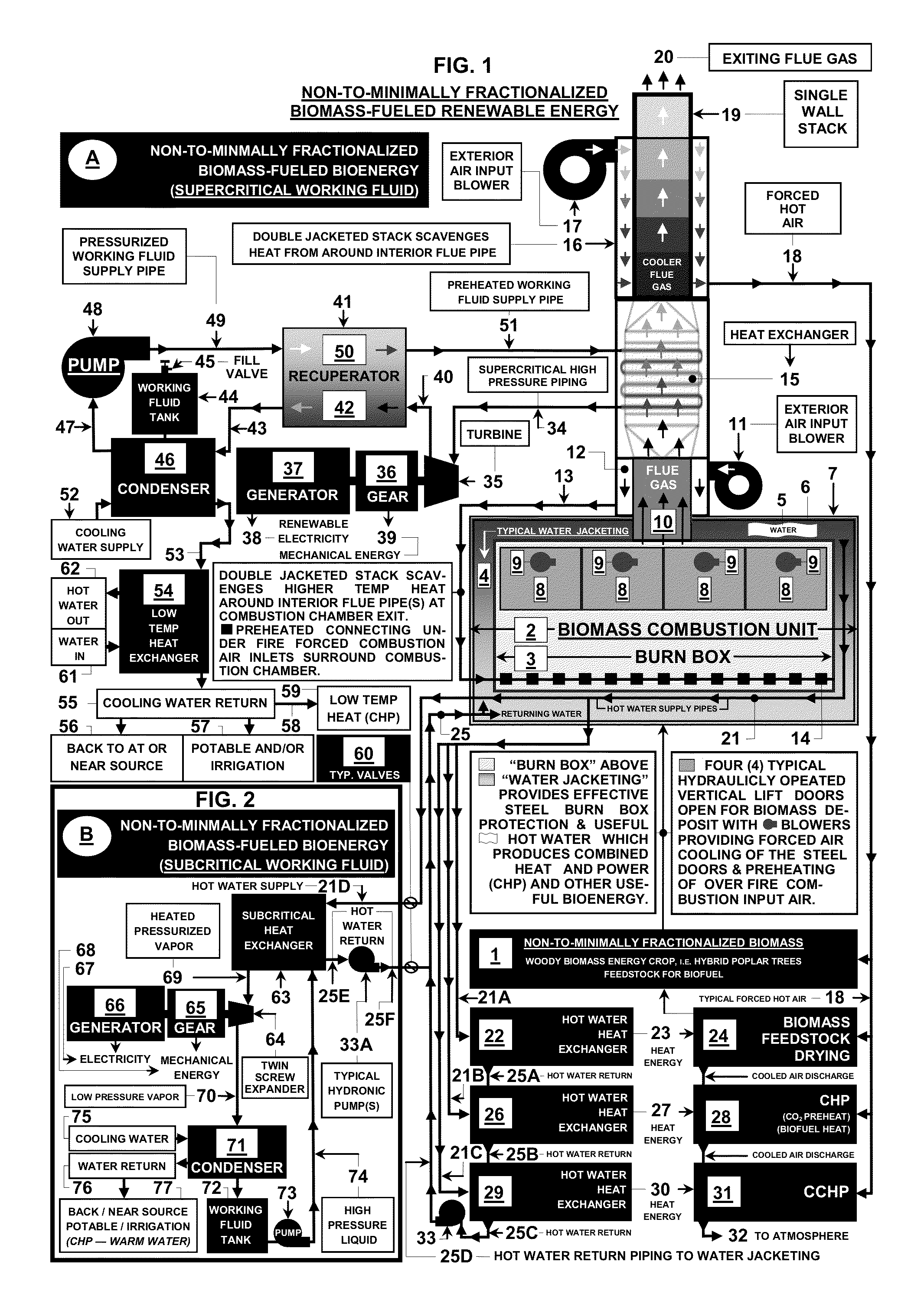
[0065]Referring to FIG. 1, presented is system A for the innovative production of “Non-To-Minimally Fractionalized Biomass-Fueled Renewable Energy” deploying a Supercritical Working Fluid obtaining the necessary heat energy needed via a novel Biomass Combustion Unit 2.

[0066]Referring to FIG. 2, further presented is system B for the additional innovative production of “Non-To-Minimally Fractionized Biomass-Fueled Renewable Energy” deploying a Subcritical Working Fluid. Syst...


PUM


Abstract

A novel Biomass Combustion Unit apparatus purposefully designed to be uniquely fueled with Non-To-Minimally Fractionalized Biomass for the intentional production of heat for conversion to a multiplicity of useful energy forms. More particularly, said apparatus provides useful heat for: (i) Power Generation, (ii) Heating Applications, (iii) Cogeneration or Combined Heat and Power (CHP), (iv) Trigeneration or Combined Cooling, Heat, and Power (CCHP), (v) Mechanical Energy and (vi) Facilitating the production of Biofuels. Additionally, methods and systems are presented wherein the abovementioned forms of energy deploy organic and inorganic working fluids, in both Subcritical and Supercritical Power Generation Cycles, via Organic Rankine Cycle and a modified Rankine Cycles, respectively. Further, Woody Biomass Energy Crops and Biofuel components are presented as well.

Description

CROSS-REFERENCE TO RELATED APPLICATIONS[0001]Not Applicable.STATEMENT REGARDING FEDERALLY SPONSORED-RESEARCH OR DEVELOPMENT[0002]Not Applicable. The Statement Regarding Federally Sponsored Research or Development previously set forth in unpublished U.S. Provisional Patent Application No. 61 / 359,781 was made in error and is again hereby withdrawn.INCORPORATION BY REFERENCE[0003]The below are each expressly incorporated herein by reference in their entireties to form a part of this application:[0004](I) U.S. Provisional Patent Application No. 61 / 359,199—filed Jun. 28, 2010, entitled: “Biomass-Fueled Refrigerant Based Electricity Generation”,[0005](II) U.S. Provisional Patent Application No. 61 / 359,781—filed Jun. 29, 2010, entitled: “Biomass-Fueled Refrigerant Based Electricity Generation”,[0006](III) U.S. patent application Ser. No. 13 / 170,828 filed Jun. 28, 2011, entitled: “Nonfractionalized Biomass-Fueled Refrigerant-Based Cogeneration” (Publication No. US-2011-0314816-A1 / Publicatio...

Claims


Application Information

Patent Timeline
Patent Type & Authority Patents(United States)
IPC IPC(8): F01K25/08F24D18/00
CPCY02E20/14Y02E50/11F24H2240/00F01K25/10F24D12/02F24H2230/00F24H4/02F24H9/0084Y02E20/12F23G7/00F01K7/32F24D2200/18F24H1/24F01K17/02Y02B30/14F23G7/10Y02B30/00F24D2101/10F24D18/00F24D2103/13Y02E50/10
Inventor JULIAN, MARVIN, DUANE
Owner JULIAN MARVIN DUANE
Why Eureka
Try Eureka