Video laryngoscope

a technology of laryngoscope and video, which is applied in the field of laryngoscope, can solve the problems of intubation difficulty, high rate of intubation difficulty or throat injury,

Active Publication Date: 2014-11-25
DING LI
View PDF7 Cites 6 Cited by
  • Summary
  • Abstract
  • Description
  • Claims
  • Application Information

AI Technical Summary

Benefits of technology

[0007]The invention also provides a method that is capable of guiding the trachea guide wire to any glottis position exposed by any electronic video laryngoscope in any difficult situations, and then guiding the endotracheal tube to complete tracheal intubation under difficult occasions.
[0018]1) The electronic video laryngoscope with a trachea cannula guide groove can be used through the observation on the color LCD mounted on the handle. The trachea guide wire can be inserted into any glottis position exposed by the video laryngoscope. The endotracheal tube can then be guided in to perform difficult intubation.2) The trachea guide wire is inserted first by means of the trachea cannula guide groove on the video laryngoscope; then, the endotracheal tube is guided in by means of the trachea guide wire. This method solves the problem that the general video laryngoscope can only expose the glottis under difficult intubation situations but difficult to insert the trachea cannula. Thus, it avoids or reduces the injury to the larynx and trachea during intubation.3) The trachea cannula guide groove is in an approximate arc curve. It is convenient to lead the guide wire into the exposed glottis;4) The cross-section of the trachea cannula guide groove is of a “kidney-shape”. The two semi-circular radius R at both ends are greater than that of the trachea guide wire. This can make the guide wire run easily in the trachea cannula guide groove and will not slip out easily.5) The opening slot provided on one side of the “kidney-shape” can let the trachea guide wire be easily removed from the trachea cannula guide groove after it is inserted into the glottis.6) The laryngoscope lens handle and LCD parts can be easily dismantled so that the laryngoscope lens can be immersed for disinfection for repeated use;7) The video laryngoscopy with a trachea cannula guide groove not only can improve the intubation exposing conditions but also reduce the injury to the larynx. It solves the problems of trachea cannula under difficult intubation with laryngoscopy.

Problems solved by technology

Although the electronic video laryngoscope improved the intubation exposure conditions, there are still intubation difficulties or throat injuries, especially for patients with high larynx, the rate of intubation difficulties or throat injuries is rather high.

Method used


Image

  • Video laryngoscope
  • Video laryngoscope
  • Video laryngoscope

Examples


Embodiment Construction

[0027]See the figures below for further illustration on the invention.

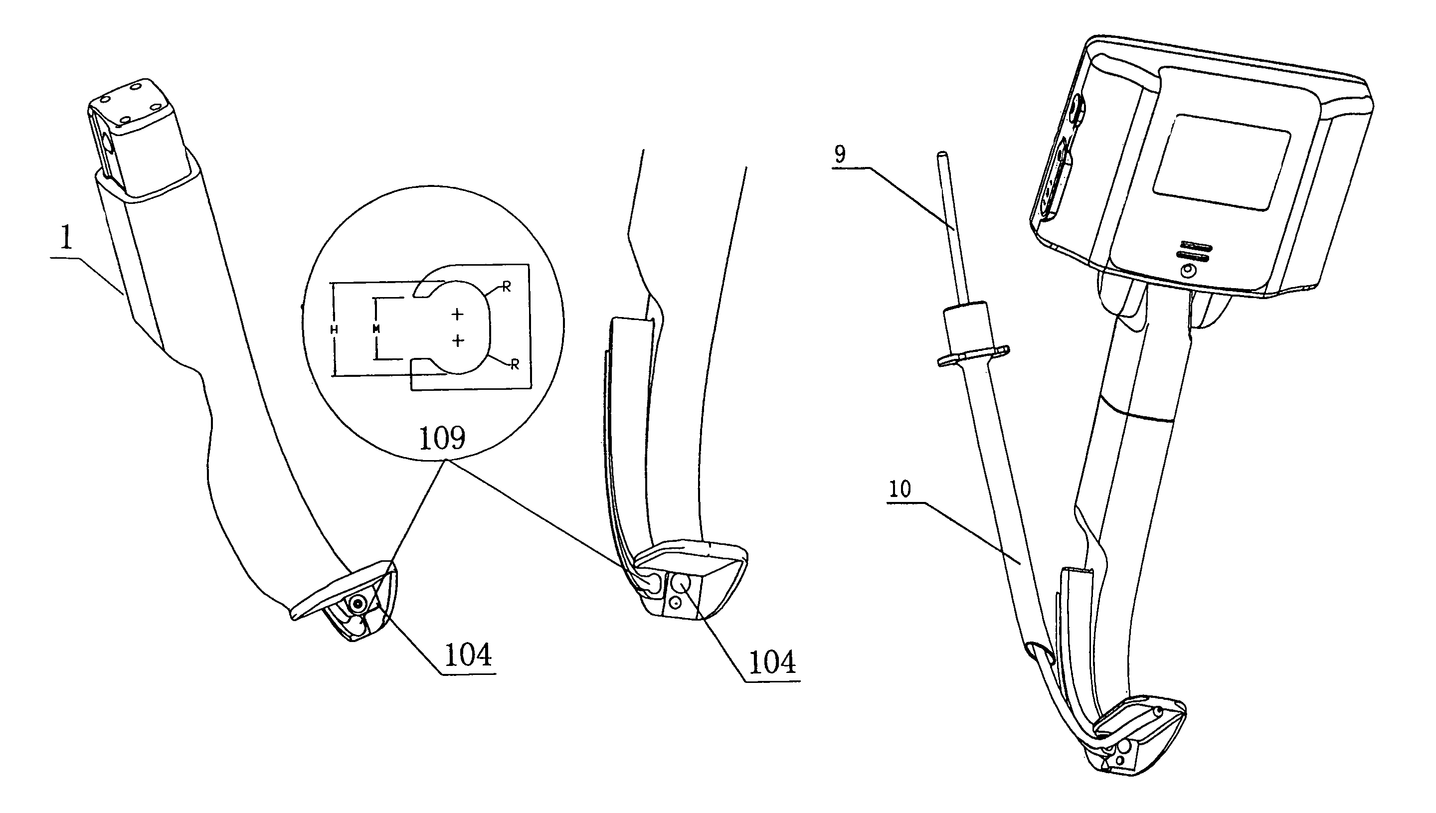
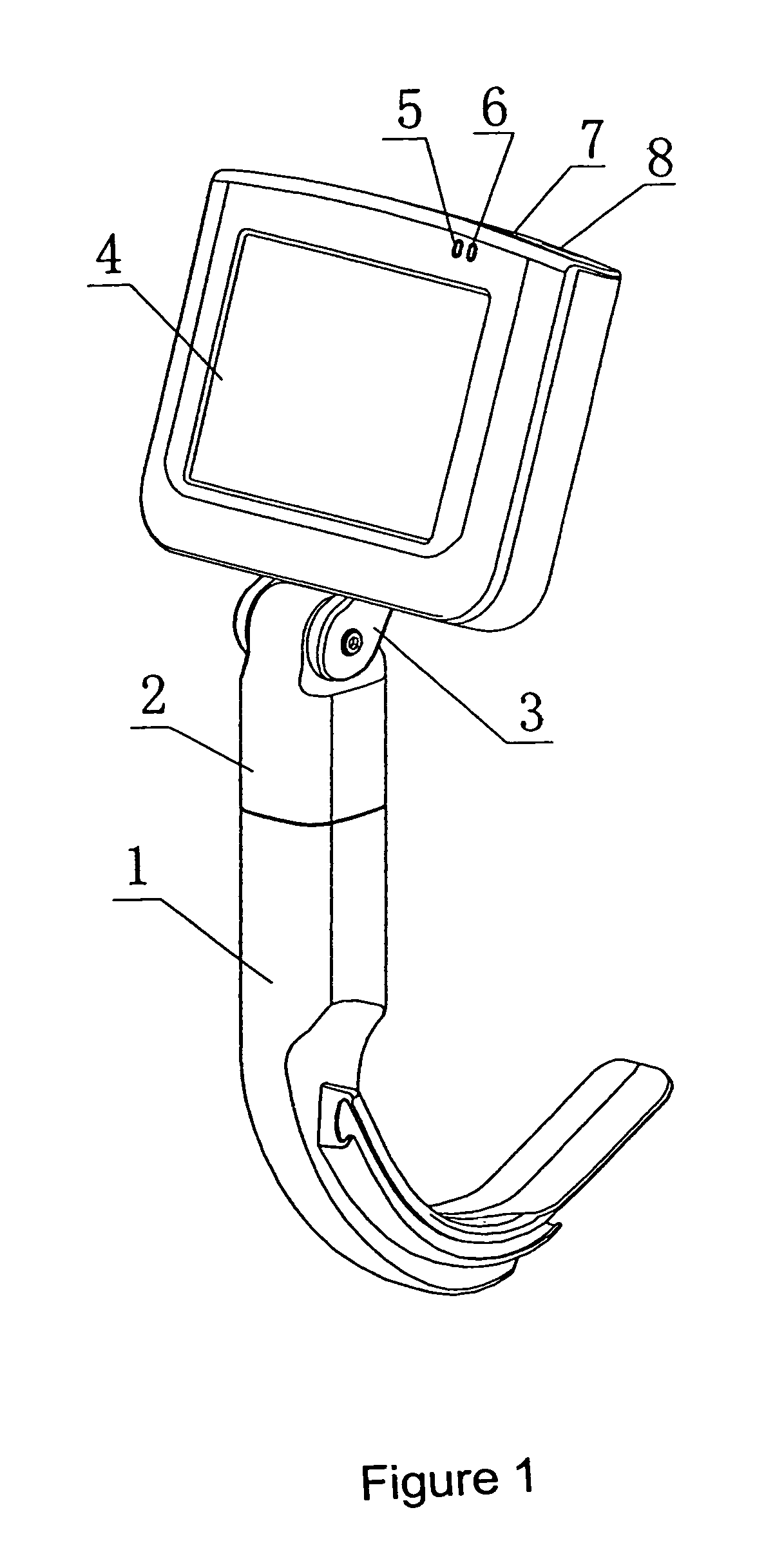
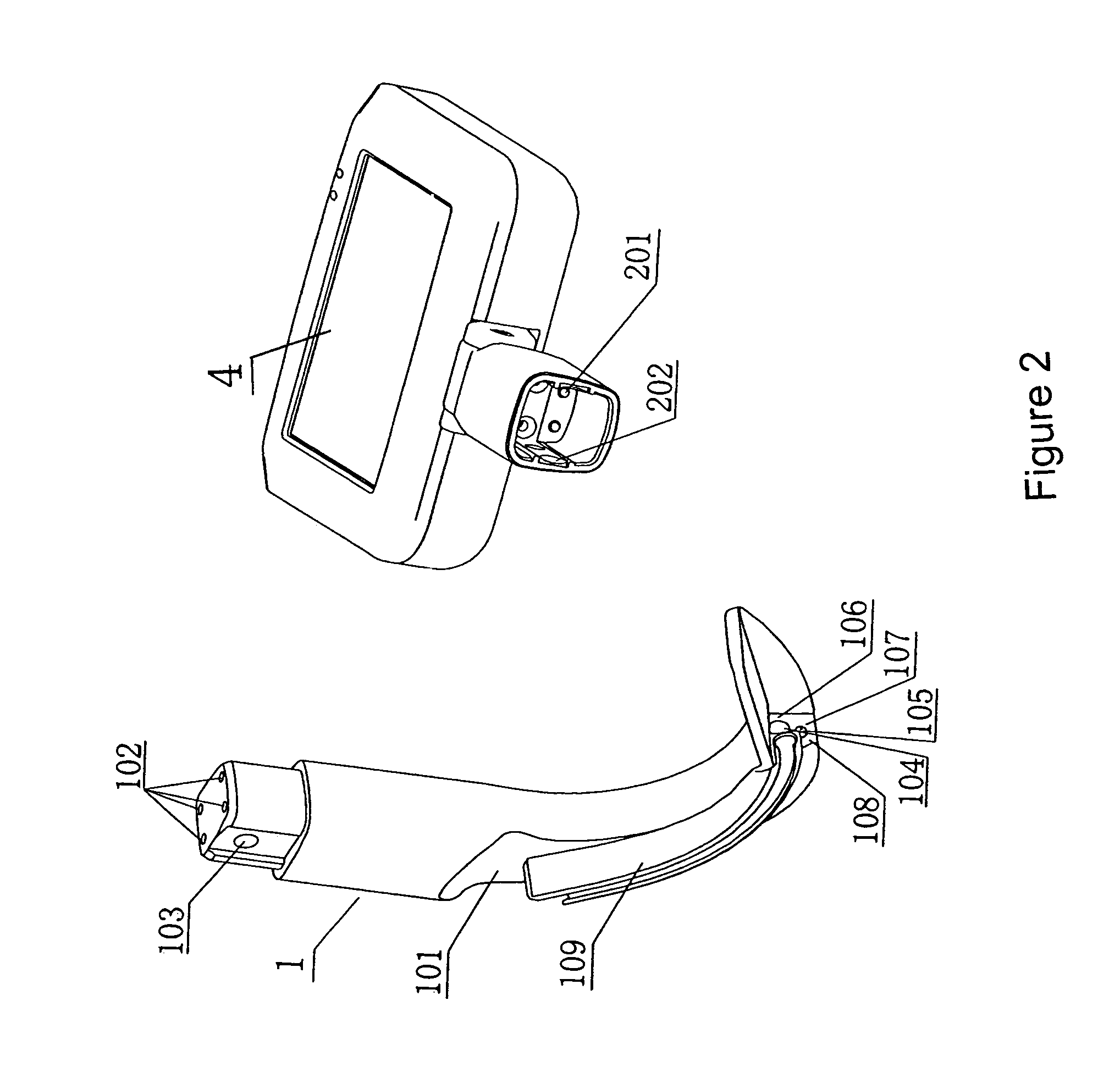
[0028]As shown in FIG. 1, FIG. 2 and FIG. 3, the invention provides a video laryngoscope with a trachea cannula guide groove for difficult intubation including a handle, a video camera and a trachea cannula guide groove laryngoscope lens 1, handle clamping sleeve 2 and liquid crystal display 4. The trachea guide groove is an arc-shape trachea cannula guide groove 109 on the laryngoscope lens 1 with handle. A trachea guide wire 9 can be put in the trachea cannula guide groove 109. After the endotracheal tube 10 is inserted with the trachea guide wire 9, the endotracheal tube 10 can be guided into the glottis 11. The trachea guide wire 9 can be separated with guide groove 109 via a breach on the side of the guide groove.

[0029]The trachea cannula guide groove 109 on the laryngoscope lens is integrated or separated with laryngoscope lens 1. The separated trachea cannula guide groove 109 can be connected to a laryngosc...


PUM


Abstract

A video laryngoscope has a handle and a groove on one side of the handle. The groove is used for guiding a guide wire when the larynogoscope is placed in a patient's mouth. A video camera located near the end of the handle is used to view the area around the glottis. When the guide wire is properly positioned near the glottis, the upper part of the guide wire is disengaged from the groove so as to allow an endotracheal tube to be slipped over the guide wire and to be inserted into part of the trachea through the glottis. When the tube is properly inserted for intubation, the guide wire is removed from the tube. An illuminating light source such as an LED lamp can be installed at the end of the handle to provide illumination for the video camera.

Description

CROSS REFERENCE TO RELATED APPLICATION[0001]This application claims priority from CN 2009 20067327.5 filed Jan. 22, 2009, CN 2009 10194495.5 filed Aug. 24, 2009, and PCT / CN2009 / 076326 filed Dec. 31, 2009.TECHNICAL FIELD[0002]The invention relates to a laryngoscope for trachea intubation in clinical anesthesia and emergency rescue occasions, particularly an electronic video laryngoscope with a trachea cannula guide groove for difficult intubation. The specially-designed trachea guide wire and guide groove structure apply to all difficult intubation occasions of trachea intubation with laryngoscope.TECHNICAL BACKGROUND[0003]Tracheal intubation is needed in clinical emergency rescue or general anesthesia occasions. However, the patient is normally in suffocation or non-breathing state at the moment. Although the electronic video laryngoscope improved the intubation exposure conditions, there are still intubation difficulties or throat injuries, especially for patients with high larynx,...

Claims


Application Information

Patent Timeline
Patent Type & Authority Patents(United States)
IPC IPC(8): A61B1/00A61B1/267A61B1/06
CPCA61B1/00073A61B1/06A61B1/00052A61B1/267
Inventor JIANG, WENQIANGDING, LI
Owner DING LI
Why Eureka
Try Eureka