Colour calibration method for an image capture device

a technology of image capture and calibration method, which is applied in the direction of optical radiation measurement, color signal processing circuit, instruments, etc., can solve the problems of difficult application of techniques, difficult process of computing such a transformation, and rare for the camera colour space to exactly match, so as to reduce the complexity of transformation and computation time

Active Publication Date: 2014-11-25
LBT INNOVATIONS
View PDF7 Cites 13 Cited by
  • Summary
  • Abstract
  • Description
  • Claims
  • Application Information

AI Technical Summary

Benefits of technology

[0013]determining an angular offset for each control point such that the distance between a transformed apparent colour and the reference colour for each colour patch is minimised, the angular offset representing a hue correction,
[0019]The angular offsets of the control points may be used to map an apparent hue to an actual hue of a pixel in any other image taken by the same image capture device under the same lighting conditions, by interpolating between the angular offsets for the control points to determine an interpolated angular offset for the apparent hue of the pixel in the image. The interpolated angular offset is then applied to the apparent hue to achieve an approximation of the actual hue (and therefore actual colour). By applying a transform in a circular hue space, the method of the present invention may provide a more accurate approximation than a straightforward linear transformation of the original colour values. It is to be understood by those persons skilled in the art that references to “actual colour” does not require that the apparent colour be mapped perfectly to the reference colour space. Rather, the mapping provides an approximation of the actual colour.
[0022]Measuring the apparent colour of a colour patch in the image captured by the image capture device may further include: measuring a colour of a colour patch, white balance correcting the measured colour, brightness correcting the measured colour, and determining the apparent colour using the resulting white balance and brightness corrected colour. The white balance correction may be done using a weighting determined from a neutral grey patch in the colour chart, where the R, G and B values should be equal. The brightness may be corrected using a curve computed using a plurality of grey patches in the colour chart which have known brightness. Thus, the colour mapping is performed with data that has been corrected for white balance and brightness. This reduces the complexity of the transformation and thus the computation time required compared with producing a mapping that accounts for white balance and brightness.
[0023]Determining the angular offset for each control point such that the distance between a transformed apparent colour and the reference colour for each colour patch is minimised may include minimising a cost function that includes the sum of the squares of the distance between the transformed apparent colour and the reference colour for each colour patch. The cost function may further include the sum of the squares of the angular offsets.
[0024]In an embodiment, the method may further include determining a scale for each control point such that the distance between a transformed apparent colour and the reference colour for each colour patch is minimised, the scale representing a saturation correction, wherein interpolation of the scales for the control points provide a further mapping from apparent colour to actual colour for the image capture device.
[0026]As above, determining the scale for each control point such that the distance between a transformed apparent colour and the reference colour for each colour patch is minimised may include minimising a cost function that includes the sum of the squares of the distance between the transformed apparent colour and the reference colour for each colour patch. The cost function may further include the sum of the squares of one minus each saturation scale to encourage final scales around one.

Problems solved by technology

However, it is rare for the camera colour space to exactly match a known reference colour space.
Computing such a transform is a difficult process, and requires a large number of colour samples, and preferably knowledge of the camera sensor itself.
Such a technique is difficult to apply in some situations where space or time constraints render such a process impractical.

Method used


Image

  • Colour calibration method for an image capture device
  • Colour calibration method for an image capture device
  • Colour calibration method for an image capture device

Examples


Embodiment Construction

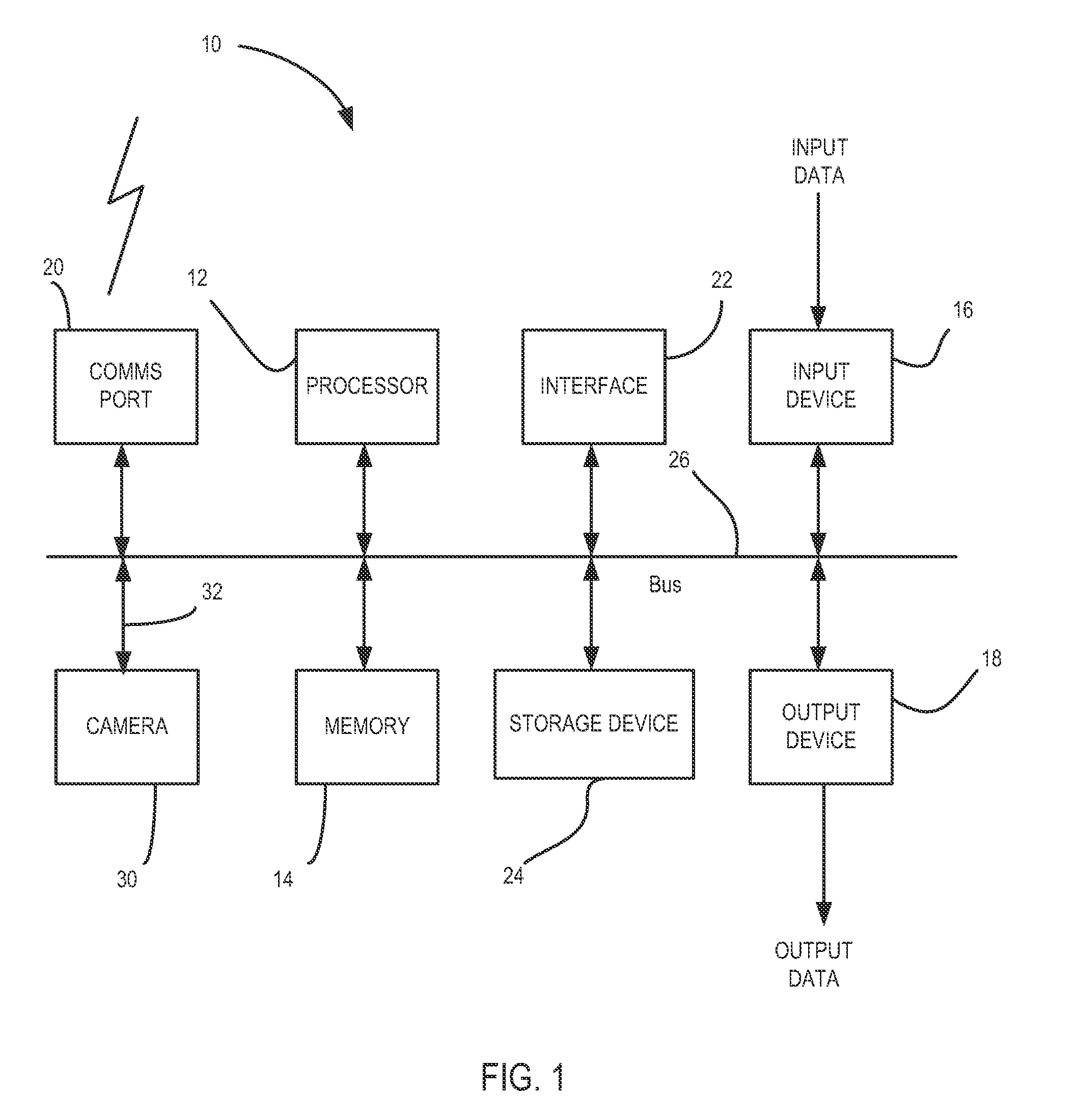
[0042]An example processing system and image capture device for use with embodiments of the invention will be described with reference to FIG. 1. The processing system 10 includes a processor 12, a memory 14, at least one input device 16, at least one output device 18, a communications port 20, an interface 22 and a storage device 24. As is shown, the components of the processing system 10 are coupled together via a bus or group of buses 26.

[0043]The processor 12 may include more than one processing device, for example to handle different functions within the processing system 10. The memory 14 may include any suitable memory device and including, for example, volatile or non-volatile memory, solid state storage devices, magnetic devices, etc. The memory 14 may store instructions for execution by the processor 12.

[0044]Input device 16 receives input data and may include, for example, a keyboard, a mouse or other pointer device, a trackball, joystick or touch-screen, a microphone, a ...


PUM


Abstract

A method for providing a mapping from apparent color to actual color for an image capture device including capturing an image of a reference color chart having a plurality of color patches using the image capture device, wherein each color patch has an associated reference color, measuring the apparent color of the plurality of color patches in the captured image, selecting a plurality of control points representing different hue values within a circular hue space, determining an angular offset for each control point such that the distance between a transformed apparent color and the reference color for each color patch is minimized, the angular offset representing a hue correction, wherein interpolation of the angular offsets for the control points provides a mapping from apparent color to actual color for the image capture device.

Description

RELATED APPLICATIONS[0001]This application claims priority to and is the U.S. National Phase of international patent application number PCT / AU2012 / 000208, International Filing Date 2 Mar. 2012, entitled Colour Calibration Method For An Image Capture Device, which claims priority to Australian Provisional Patent Application No. 2011900785 filed on 4 Mar. 2011, entitled Colour Calibration Method For An Image Capture Device, both of which are incorporated herein by reference in their entireties.FIELD OF THE INVENTION[0002]The present invention relates to methods and software for providing a mapping from apparent colour to actual colour for an image capture device, and methods and software for using the mapping in colour calibrating images captured by the device.BACKGROUND TO THE INVENTION[0003]A digital camera, in an existing example, captures an image using a sensor such as a charge-coupled device (CCD) or a Complementary Metal-Oxide Semiconductor (CMOS) sensor. Most of these camera s...

Claims


Application Information

Patent Timeline
Patent Type & Authority Patents(United States)
IPC IPC(8): H04N5/57H04N9/68H04N9/73H04N9/64H04N17/02
CPCH04N17/002G01J3/52H04N1/6033H04N9/735H04N1/6075G01J3/465H04N1/6005G01J3/462G01J3/524H04N9/643H04N9/67H04N23/12H04N23/88
Inventor VAN DEN HENGEL, ANTON JOHNHILL, RHYS ERNST
Owner LBT INNOVATIONS
Why Eureka
Try Eureka