Flexible piezocapacitive and piezoresistive force and pressure sensors
a piezocapacitive and piezo-resistive force and pressure sensor technology, applied in the field of sensors, can solve the problems of affecting tissue damage, affecting internal tissue damage, and generating damagingly large shear stresses, so as to reduce hysteria, increase linear response of sensor, and improve linearity
- Summary
- Abstract
- Description
- Claims
- Application Information
AI Technical Summary
Benefits of technology
Problems solved by technology
Method used
Image
Examples
example 1
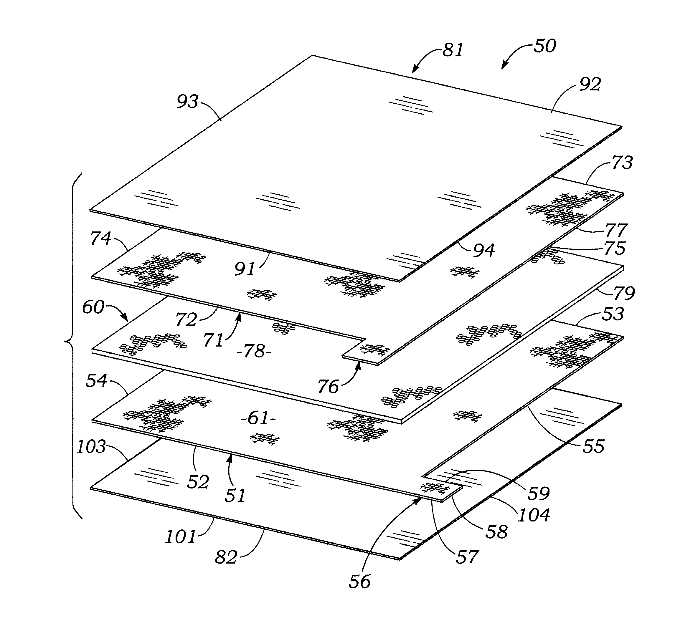
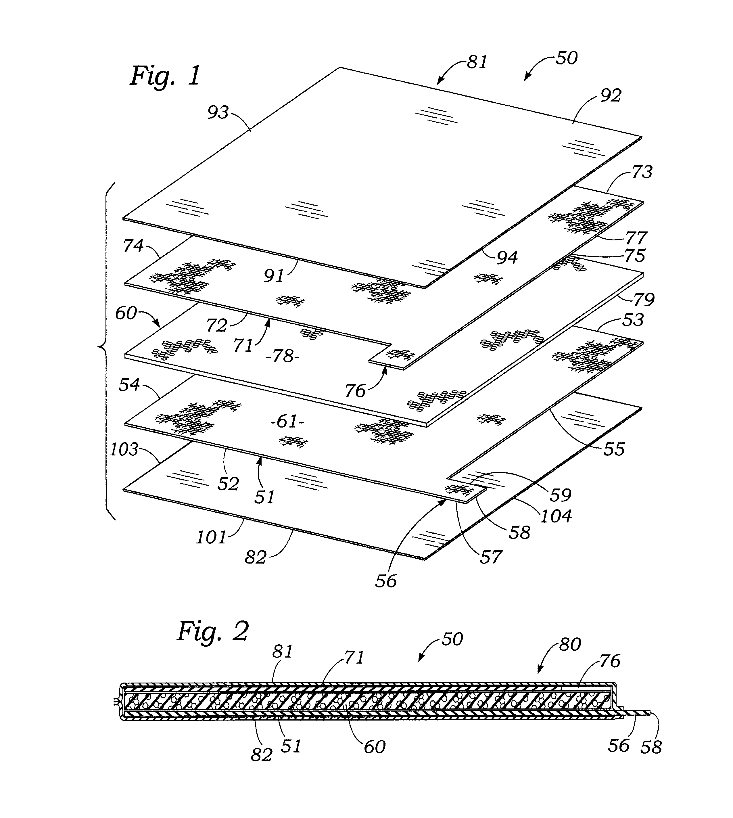
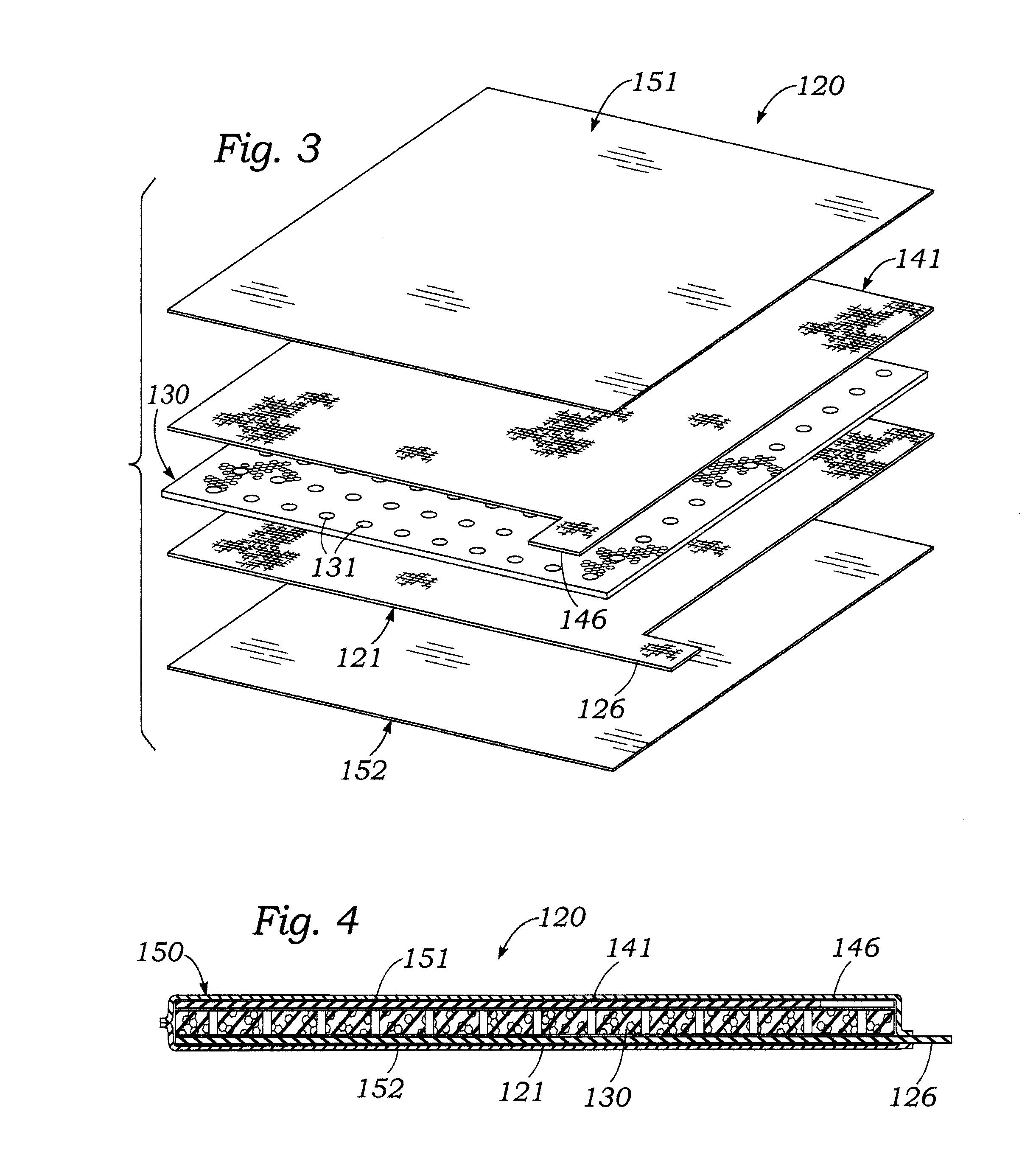
[0067]FIGS. 1 and 2 illustrate a basic embodiment of a piezocapacitive force sensor according to the present invention. FIGS. 3 and 4 illustrate a first modification of the embodiment of FIGS. 1 and 2, which has a perforated foam dielectric layer. FIGS. 5 and 6 illustrate a basic embodiment of a hybrid piezocapacitive-piezoresistive force sensor according to the present invention. FIGS. 7 and 8 illustrate a variation of the hybrid sensor of FIGS. 5 and 6, which has a single layer which is both piezocapacitive and piezoresistive.
[0068]Referring first to FIGS. 1 and 2, it may be seen that a basic embodiment 50 of a piezocapacitive force / pressure sensor according to the present invention includes a first, base, lower or inner flexible conductive sheet 51 which functions as the first conductive plate of a capacitor. Base conductive sheet 51 is preferably made of a thin, flexible, elasticity stretchable fabric which is electrically conductive. In an example embodiment of sensor 50, base ...
example 2
Perforated Pad
[0089]FIGS. 3 and 4 illustrate a modification 120 of the sensor 50 shown in FIGS. 1 and 2. Modified sensor 120 is substantially similar in construction and function to sensor 50, with the primary difference being that the central dielectric pad 130 of sensor 120 contains perforations. In an example embodiment of sensor 120, central dielectric pad 130 had over its full area an array of circular holes 131 through the thickness dimension of the pad. Each hole had a diameter of ½ inch and was spaced apart by ¼ inch from adjacent holes. The holes 131 occupied about 50 percent of the surface area of the pads.
[0090]FIG. 11A is a plot of capacitance versus applied pressure for sensor 120 shown in FIGS. 3 and 4.
[0091]Table 2A lists values of capacitance measured by a capacitance meter of the sensor 120 shown in FIGS. 3 and 4 as a function of increasing applied pressure.
[0092]
TABLE 2ACAPACITANCE VS PRESSURE OF EXAMPLE 2 (FIGS. 3 & 4)Pressure, psiCapacitance, nf000.1660.20.8331.7...
example 3
Perforated Pad Saturated with Glycerine
[0095]FIG. 12A and table 3 show the variation of capacitance versus external force or pressure for a first variation 120A of the sensor 120 (Example 3) of FIGS. 3 and 4, in which the central perforated dielectric pad 130 thereof had a weight of about 1 gram and was saturated with 2 grams of glycerin.
[0096]
TABLE 3CAPACITANCE VS PRESSURE OF EXAMPLE 3 (FIGS. 3 & 4Pressure, psiCapacitance, nf060.16680.833141.336.252.118
PUM
| Property | Measurement | Unit |
|---|---|---|
| thick | aaaaa | aaaaa |
| frequency | aaaaa | aaaaa |
| thickness | aaaaa | aaaaa |
Abstract
Description
Claims
Application Information
 - R&D
- Intellectual Property
- Life Sciences
- Materials
- Tech Scout
- Unparalleled Data Quality
- Higher Quality Content
- 60% Fewer Hallucinations
Browse by: Latest US Patents, China's latest patents, Technical Efficacy Thesaurus, Application Domain, Technology Topic, Popular Technical Reports.
© 2025 PatSnap. All rights reserved.Legal|Privacy policy|Modern Slavery Act Transparency Statement|Sitemap|About US| Contact US: help@patsnap.com


