Flexible Piezocapacitive And Piezoresistive Force And Pressure Sensors

a piezocapacitive and piezoresistive force and pressure sensor technology, applied in the field of sensors, can solve the problems of affecting tissue damage, high pressure alone is generally not sufficient to deleteriously affect tissue, and affecting internal tissue damage, so as to reduce hysteria, increase linear response of sensor, and improve linearity

Inactive Publication Date: 2014-04-03
PATIENTECH LLC
View PDF13 Cites 101 Cited by
  • Summary
  • Abstract
  • Description
  • Claims
  • Application Information

AI Technical Summary

Benefits of technology

[0020]An object of the present invention is to provide thin, flexible force or pressure sensors which are conformable to objects having complex, compoundly curved shapes such as human body parts, to facilitate measuring and mapping forces or pressures exerted on such objects, and which have a wide dynamic range.

Problems solved by technology

Forces exerted on body parts by support surfaces, which are equal and opposite to body weight forces, can in some cases cause damage to tissues.
High pressures alone are generally not sufficient to deleteriously affect tissue.
Thus, even relatively small external shear and normal forces, which may be independent of one another, can combine to produce damagingly large shear stresses on internal tissue.
For example, if typical previously existing flexible sensor arrays are used to measure pressures exerted on a human body by a very form-fitting, conformal wheelchair seat cushion or extremely low pressure bed mattress or cushion, such sensor arrays often interfere with the function of the cushion or bed support surface, and give erroneous force measurements which are used to map the way the bed or chair supports a person.
Such errors result from a “hammocking” effect, in which a flexible but not drapable sensor array deployed between fixed support positions cannot conform precisely to the shape of a patient.
The lack of conformability of a sensor array alters the way a cushion or bed supports a patient, and also frequently results in forces or pressures exerted on individual sensors in the array being larger than a patient would actually encounter in the absence of the sensor array.
Another situation in which previous force sensor arrays for measuring and mapping forces exerted on human body parts are less than satisfactory occurs when attempting to make such measurements in a non-obtrusive, non-interfering manner on body parts which have complex shapes such as the feet.
For example, people who have diabetes often lose feeling sensation in their feet.
Since they cannot feel when an ill-fitting shoe is exerting excessive pressure on parts of the foot, the pressure spots can lead to ulcers, which may in turn necessitate amputation of the foot.

Method used


Image

  • Flexible Piezocapacitive And Piezoresistive Force And Pressure Sensors
  • Flexible Piezocapacitive And Piezoresistive Force And Pressure Sensors
  • Flexible Piezocapacitive And Piezoresistive Force And Pressure Sensors

Examples


example 1

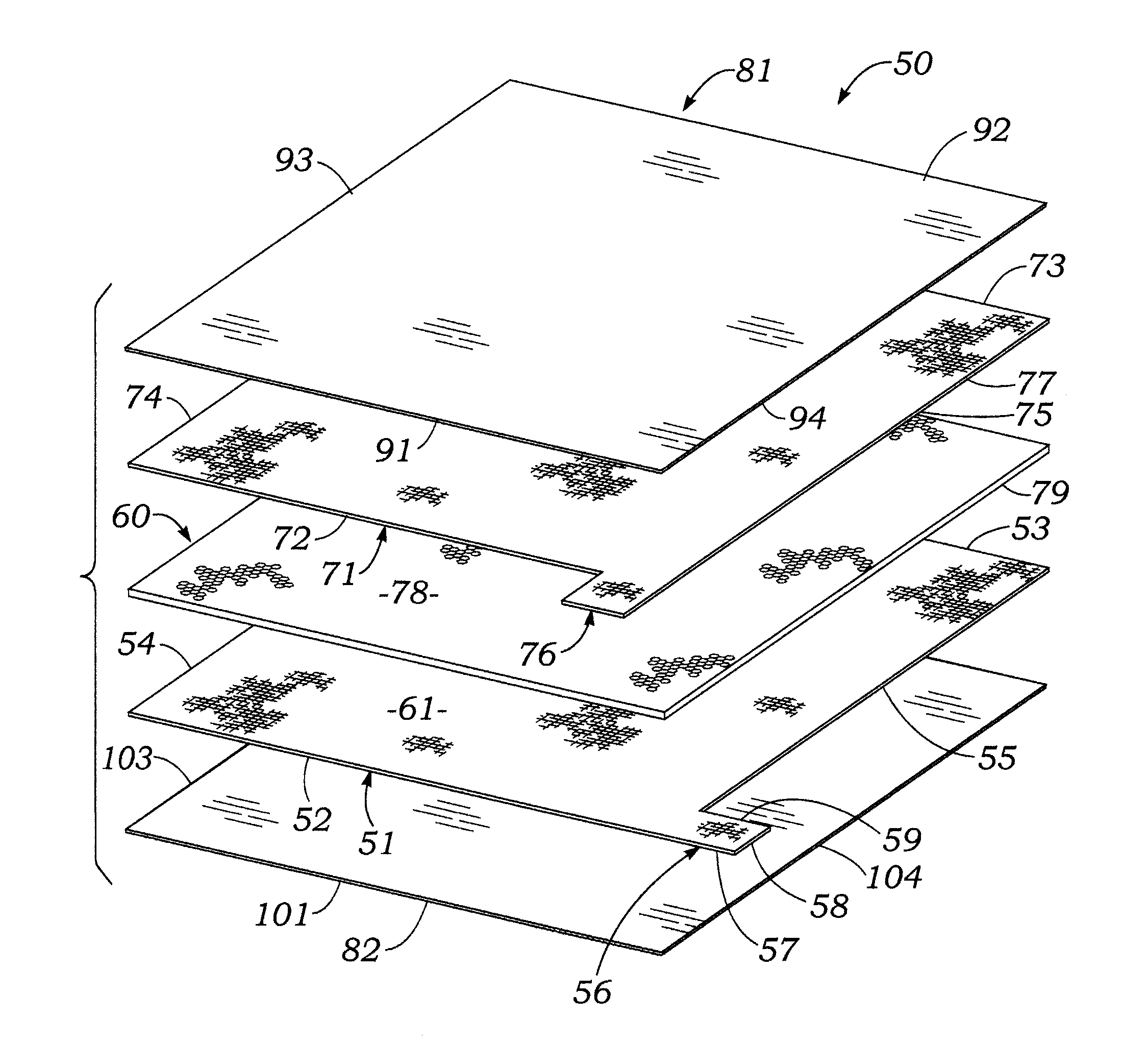
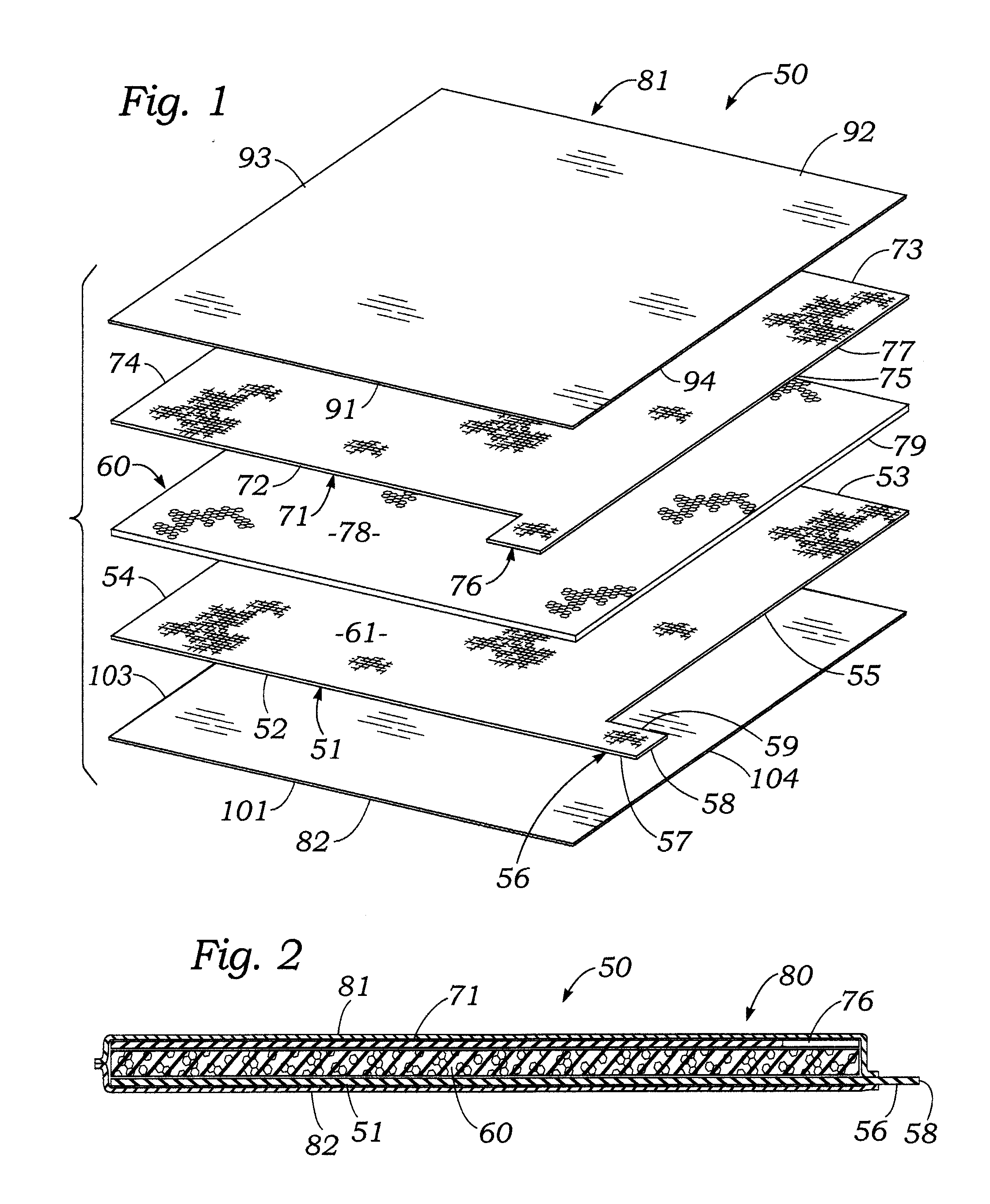
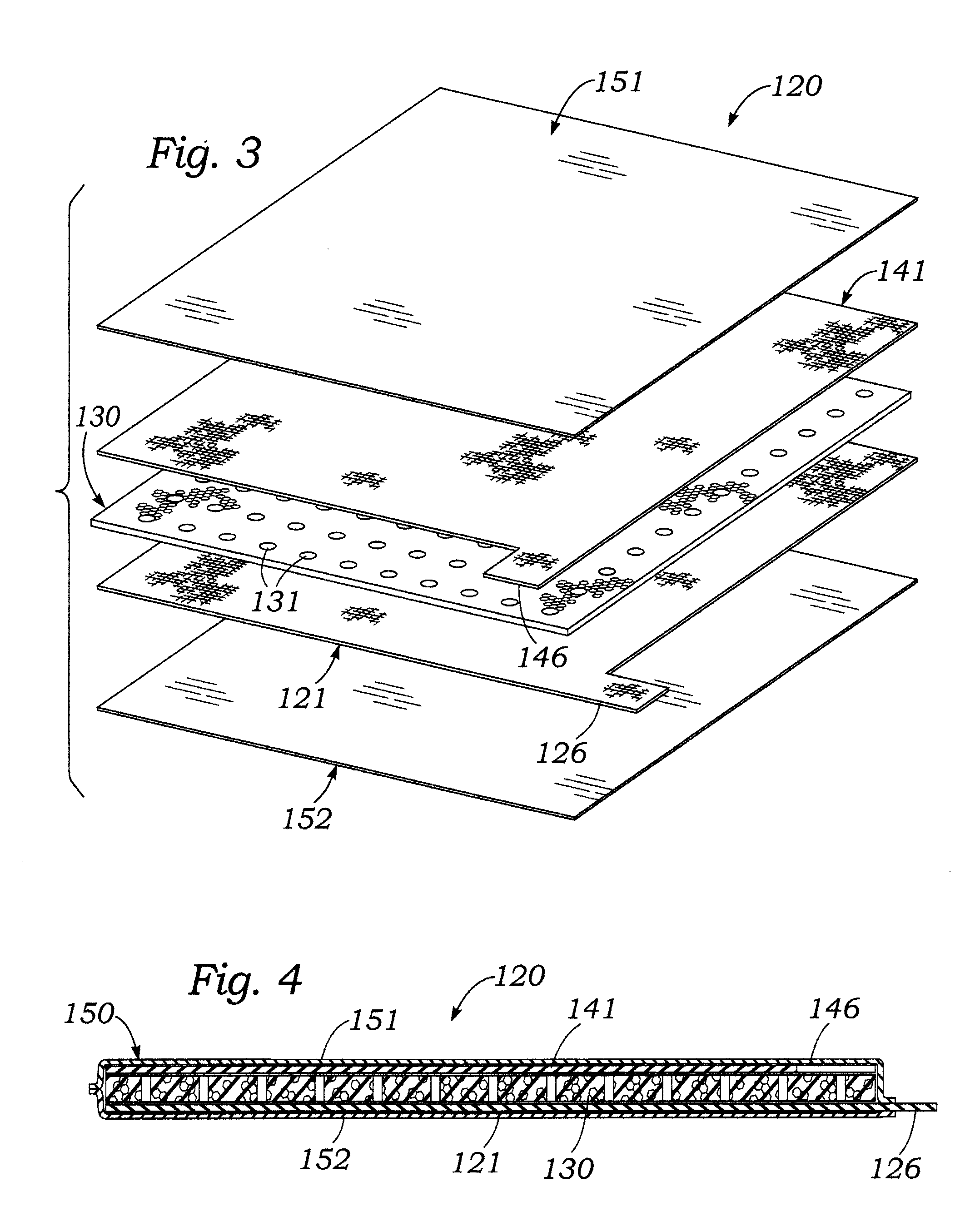
[0066]FIGS. 1 and 2 illustrate a basic embodiment of a piezocapacitive force sensor according to the present invention. FIGS. 3 and 4 illustrate a first modification of the embodiment of FIGS. 1 and 2, which has a perforated foam dielectric layer. FIGS. 5 and 6 illustrate a basic embodiment of a hybrid piezocapacitive-piezoresistive force sensor according to the present invention. FIGS. 7 and 8 illustrate a variation of the hybrid sensor of FIGS. 5 and 6, which has a single layer which is both piezocapacitive and piezoresistive.

[0067]Referring first to FIGS. 1 and 2, it may be seen that a basic embodiment 50 of a piezocapacitive force / pressure sensor according to the present invention includes a first, base, lower or inner flexible conductive sheet 51 which functions as the first conductive plate of a capacitor. Base conductive sheet 51 s preferably made of a thin, flexible, elasticity stretchable fabric which is electrically conductive. In an example embodiment of sensor 50, base c...

example 2

Perforated Pad

[0086]FIGS. 3 and 4 illustrate a modification 120 of the sensor 50 shown in FIGS. 1 and 2. Modified sensor 120 is substantially similar in construction and function to sensor 50, with the primary difference being that the central dielectric pad 130 of sensor 120 contains perforations. In an example embodiment of sensor 120, central dielectric pad 130 had over its full area an array of circular holes 131 through the thickness dimension of the pad. Each hole had a diameter of ½ inch and was spaced apart by ¼ inch from adjacent holes. The holes 131 occupied about 50 percent of the surface area of the pads.

[0087]FIG. 11A is a plot of capacitance versus applied pressure for sensor 120 shown in FIGS. 3 and 4.

[0088]Table 2A lists values of capacitance measured by a capacitance meter of the sensor 120 shown in FIGS. 3 and 4 as a function of increasing applied pressure.

TABLE 2ACAPACITANCE VS PRESSURE OF EXAMPLE 2 (FIGS. 3 & 4)Pressure, psiCapacitance, nf000.1660.20.8331.751.334...

example 3

Perforated Pad Saturated with Glycerine

[0090]FIG. 12A and table 3 show the variation of capacitance versus external force or pressure for a first variation 120A of the sensor 120 (Example 3) of FIGS. 3 and 4, in which the central perforated dielectric pad 130 thereof had a weight of about 1 gram and was saturated with 2 grams of glycerin.

TABLE 3CAPACITANCE VS PRESSURE OF EXAMPLE 3 (FIGS. 3 & 4Pressure, psiCapacitance, nf060.16680.833141.336.252.118


PUM

PropertyMeasurementUnit
thickaaaaaaaaaa
frequencyaaaaaaaaaa
thicknessaaaaaaaaaa

Abstract

Flexible force / pressure sensors for producing electrical output signals proportional to forces or pressures exerted on the sensor include a thin, elastically deformable foam pad laminated between a pair of electrically conducive fabric sheets. A piezocapacitive embodiment of the sensor utilizes an elastically deformable perforated open-cell polyurethane foam pad preferably saturated with glycerin to increase the capacitance of the sensor. The piezocapacitive sensor section is preferably stacked onto a piezoresistive section having a second open-cell foam pad containing piezoresistive carbon particles to form a hybrid piezocapacitive / piezoresistive sensor. A third, “leaky dielectric” embodiment of a sensor includes a single open-cell foam pad which contains both a dielectric liquid and conductive particles. A low frequency such as d.c. to a few hertz is applied to a sensor to determine piezoresistive response of the sensor to forces or pressures and a higher frequency such as 30 KHz is applied to determine piezocapactive response.

Description

BACKGROUND OF THE INVENTION[0001]A. Field of the Invention[0002]The present invention relates to sensors for measuring forces or pressures exerted on a surface. More particularly, the invention relates to novel flexible hybrid force sensors which vary both in resistance and capacitance in response to forces or pressures applied to the sensors, and a pressure measurement apparatus which includes a novel hybrid force / pressure sensor and circuitry for measuring electrical impedances of the sensor at different frequencies.[0003]B. Description of Background Art[0004]There are a wide variety of situations which require the accurate measurement of forces or pressures exerted at various parts of the surface of an object. For example, when a human body is supported by an object such as a chair or bed, normal and shear forces produced in reaction to the weight of an individual are transmitted from the supporting surface through the skin, adipose tissues, muscles, etc. to the skeleton. Forces ...

Claims


Application Information

Patent Timeline
Patent Type & Authority Applications(United States)
IPC IPC(8): G01L1/18G01L1/00
CPCG01L1/18G01L9/12G01L1/144
Inventor TAYLOR, GEOFFREY L.CHAPIN, WILLIAM L.
Owner PATIENTECH LLC
Why Eureka
Try Eureka