
Switch device and timepiece including switch device

a switch device and switch technology, applied in the direction of normal winding, instruments, horology, etc., can solve the problems of deficient operability of the operating member and inability to remove the lock

Active Publication Date: 2014-12-09
CASIO COMPUTER CO LTD
View PDF9 Cites 64 Cited by
  • Summary
  • Abstract
  • Description
  • Claims
  • Application Information

AI Technical Summary

Benefits of technology

[0014]An object of the present invention is to provide a switch device by which an unlock operation can be easily performed and inadvertent rotation of an operating member in a locked state can be prevented, and a timepiece including the switch device.

Problems solved by technology

However, in this switch device, when the lock on the operating member is to be released, the engaging projection of the ring member positioned in the lock groove cannot be detached from the lock groove unless the operating member is rotated while being pushed inward.
Therefore, the operability of the operating member is deficient.
Also, when the operating member is in the locked state, if the outer end thereof hits some object and is inadvertently rotated, the lock on the operating member is released, which may cause an erroneous operation.

Method used


Image

  • Switch device and timepiece including switch device
  • Switch device and timepiece including switch device
  • Switch device and timepiece including switch device

Examples


first embodiment

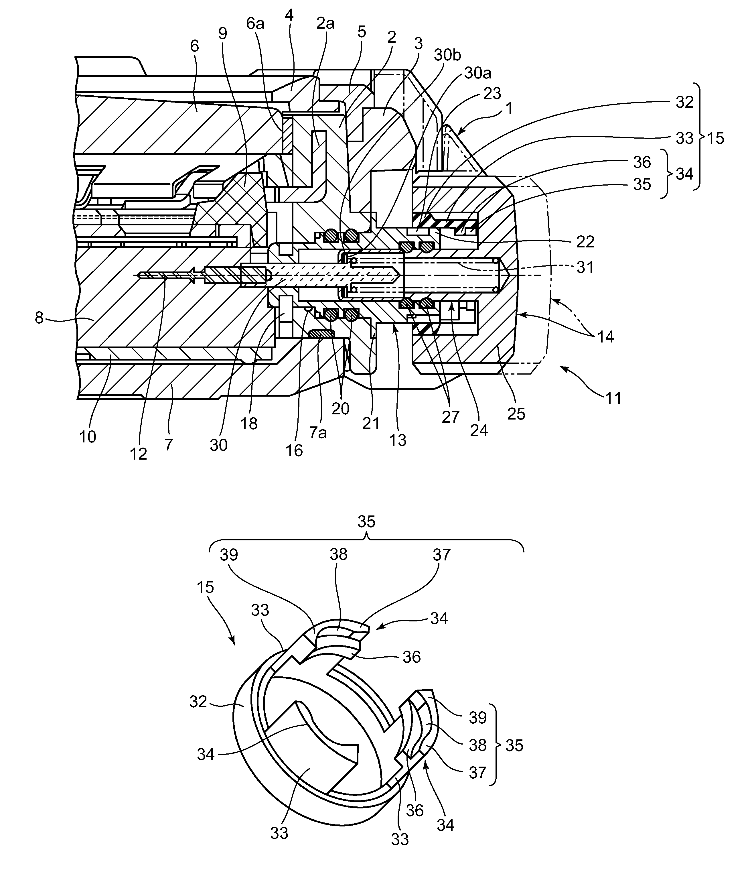
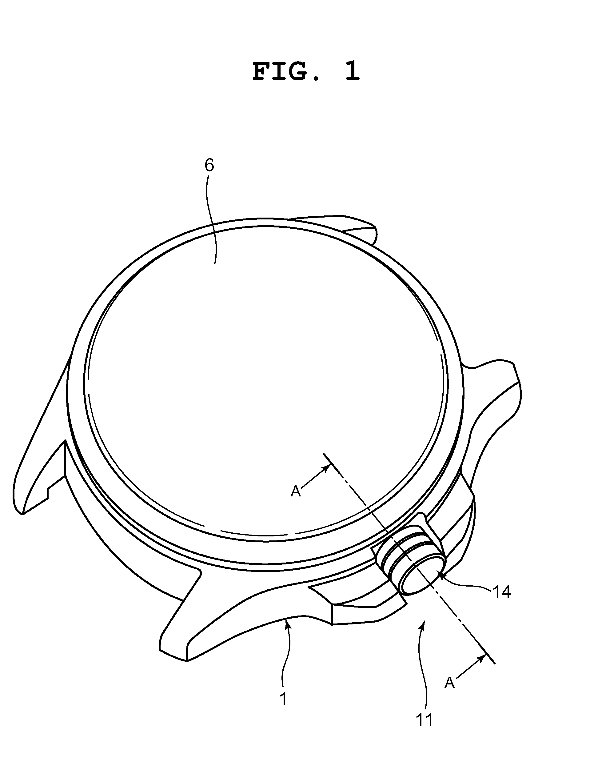
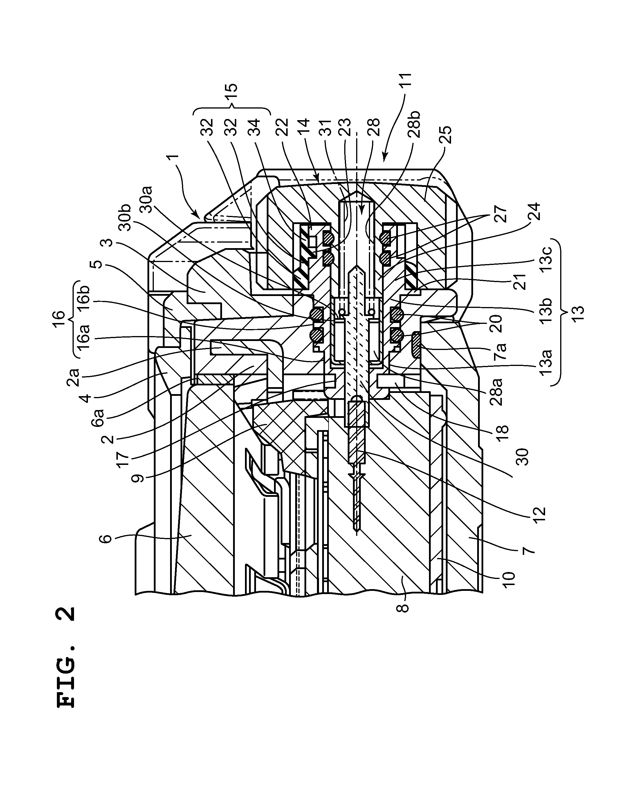
[0033]A first embodiment in which a switch device of the present invention has been applied in a wristwatch is described below with reference to FIG. 1 to FIG. 10.

[0034]This wristwatch includes a wristwatch case 1, as depicted in FIG. 1 to FIG. 3. The wristwatch case 1 includes a case body 2, a bezel 3, and a decorative panel 4.

[0035]The case body 2 is made of synthetic resin, and has provided therein a reinforcing member 2a made of metal, as depicted in FIG. 2 and FIG. 3.

[0036]The bezel 3 is made of synthetic resin such as urethane resin, and provided on the outer circumferential surface of the case body 2. The decorative panel 4 is made of a metal plate, and mounted on the upper surface of the case body 2 by a pressure ring 5.

[0037]In an opening in the upper portion of the case body 2 of the wristwatch case 1, a timepiece glass 6 is attached via a gasket 6a, as depicted in FIG. 2 and FIG. 3.

[0038]On the lower portion of the case body 2 of the wristwatch case 1, a rear lid 7 is mou...

second embodiment

[0139]Next, a second embodiment in which a switch device of the present invention has been applied in a wristwatch is described with reference to FIG. 11 to FIG. 15.

[0140]Note that sections identical to those in the first embodiment depicted in FIG. 1 to FIG. 10 are provided with the same reference numerals simplification of description.

[0141]The structure of this switch device 40 for a wristwatch is substantially the same as that of the first embodiment except that engaging projections 41 and a lock member 42 of its cylindrical member 13 are different from those of the first embodiment, as depicted in FIG. 11 and FIG. 12.

[0142]As with the first embodiment, the switch device 40 is provided on the side portion of the wristwatch case 1 on the three o'clock side.

[0143]Also, the switch device 40 is to switch the mode of the timepiece module 8, adjust the time, and the like, and includes the winding stem 12, the cylindrical member 13, the operating member 14, and the lock member 15, as w...


PUM


Abstract

A switch device of the present invention includes a cylindrical member fitted into a through hole of a wristwatch case, an operating member having an operation shaft section to be inserted into the cylindrical member and an operation head section, and a lock member fixed inside the operation head section. The cylindrical member includes engaging projections, and the lock member includes resilient support sections which have a space with respect to the inner circumferential surface of the operation head section and are resiliently deformed in a radial direction, and lock sections with which the engaging projections are resiliently engaged. Accordingly, when the operating member is pushed inward and rotated, the engaging projections resiliently deform the resilient support sections and are engaged with the lock sections. Also, only by the operating member being rotated against the regulating force of the lock section, the lock sections are disengaged from the engaging projections.

Description

CROSS-REFERENCE TO RELATED APPLICATION[0001]This application is based upon and claims the benefit of priority from the prior Japanese Patent Application No. 2013-058455, filed Mar. 21, 2013, the entire contents of which is incorporated herein by reference.BACKGROUND OF THE INVENTION[0002]1. Field of the Invention[0003]The present invention relates to a switch device for use in a timepiece such as a wristwatch, and a timepiece including the switch device.[0004]2. Description of the Related Art[0005]For example, a wristwatch is known which includes a switch device where an operating member such as a crown has been provided in a wristwatch case such that it can be pulled outward, as described in Japanese Patent Application Laid-Open (Kokai) Publication No. 2006-194834.[0006]This type of switch device is structured such that the time can be adjusted by the operating member, which is protruding from the wristwatch case, being pulled outward and rotated in this state.[0007]In this structu...

Claims


Application Information

Patent Timeline
Patent Type & Authority Patents(United States)
IPC IPC(8): G04B29/00G04B3/04
CPCG04B3/043
Inventor SAKURAZAWA, NAOHIKOIMAI, HIROKI
Owner CASIO COMPUTER CO LTD
Learn More