Eureka AIR delivers breakthrough ideas for toughest innovation challenges, trusted by R&D personnel around the world.

Method and circuit for LED load managment

a driver circuit and load technology, applied in the direction of electric variable regulation, process and machine control, instruments, etc., can solve the problems of unstable load operation, instant and permanent damage to leds,

Inactive Publication Date: 2015-01-06
UNIVERSAL LIGHTING TECHNOLOGIES
View PDF2 Cites 1 Cited by
  • Summary
  • Abstract
  • Description
  • Claims
  • Application Information

AI Technical Summary

Problems solved by technology

When an LED load is reattached to a driver circuit that is generating an abnormally high output voltage, the LED load experiences high surge currents which can instantly and permanently damage the LEDs.
Functioning outside of nominal operation can damage power transfer components of the driver circuit or cause the load to operate in an unstable manner.

Method used


Image

  • Method and circuit for LED load managment
  • Method and circuit for LED load managment
  • Method and circuit for LED load managment

Examples


Embodiment Construction

[0017]Reference will now be made in detail to optional embodiments of the invention, examples of which are illustrated in accompanying drawings. Whenever possible, the same reference numbers are used in the drawing and in the description referring to the same or like parts.

[0018]While the making and using of various embodiments of the present invention are discussed in detail below, it should be appreciated that the present invention provides many applicable inventive concepts that can be embodied in a wide variety of specific contexts. The specific embodiments discussed herein are merely illustrative of specific ways to make and use the invention and do not delimit the scope of the invention.

[0019]To facilitate the understanding of the embodiments described herein, a number of terms are defined below. The terms defined herein have meanings as commonly understood by a person of ordinary skill in the areas relevant to the present invention. Terms such as “a,”“an,” and “the” are not i...


PUM


Abstract

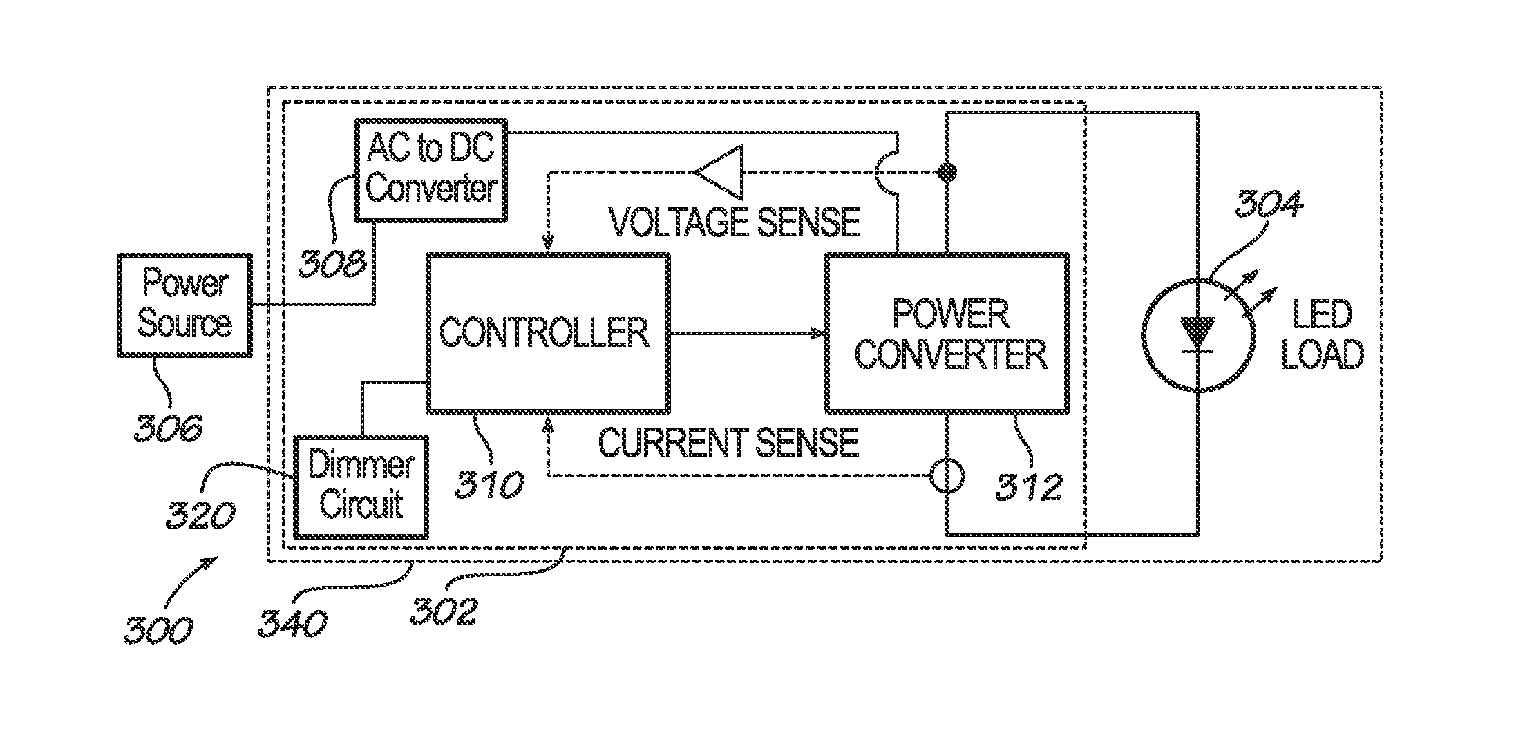
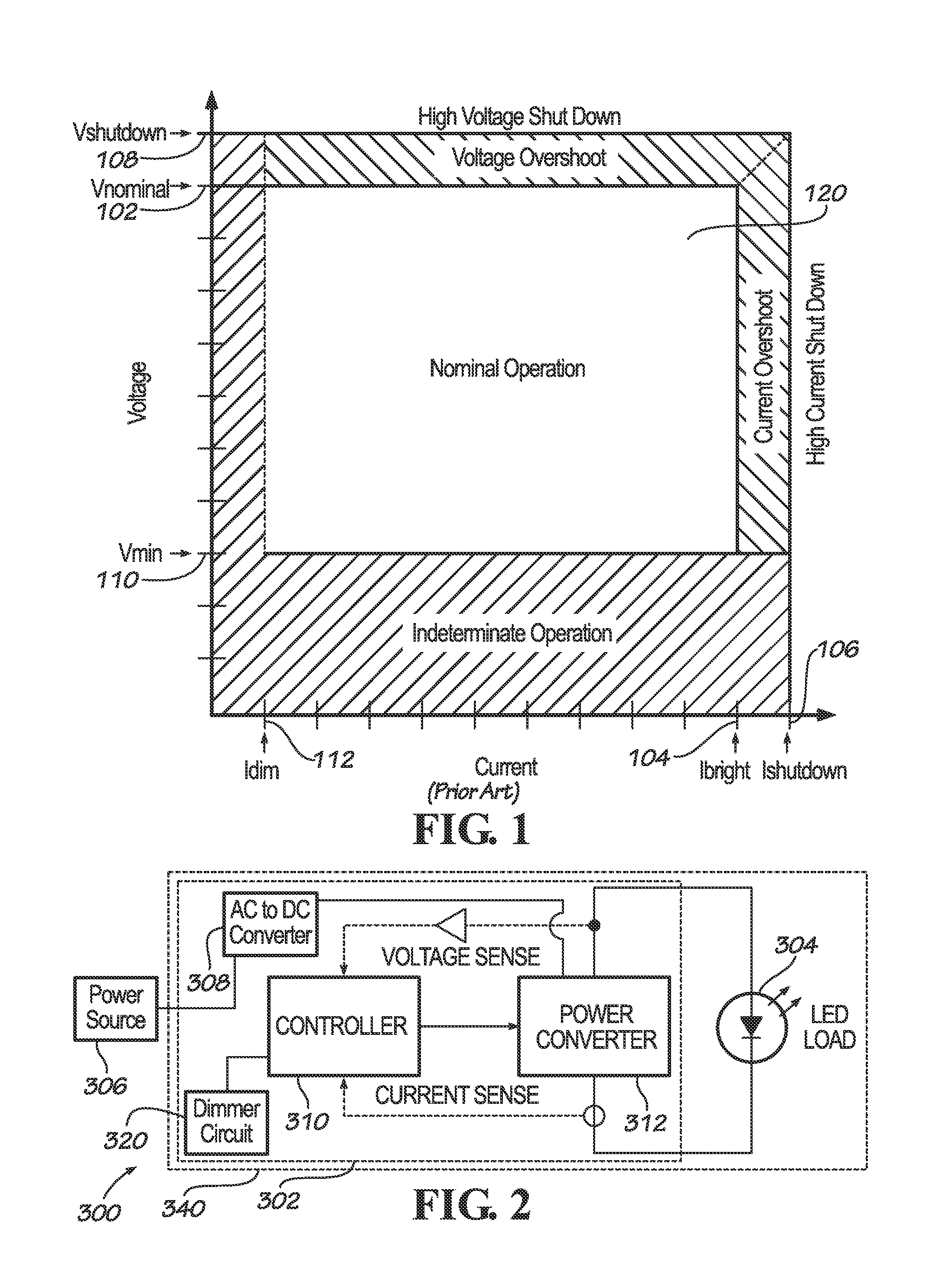
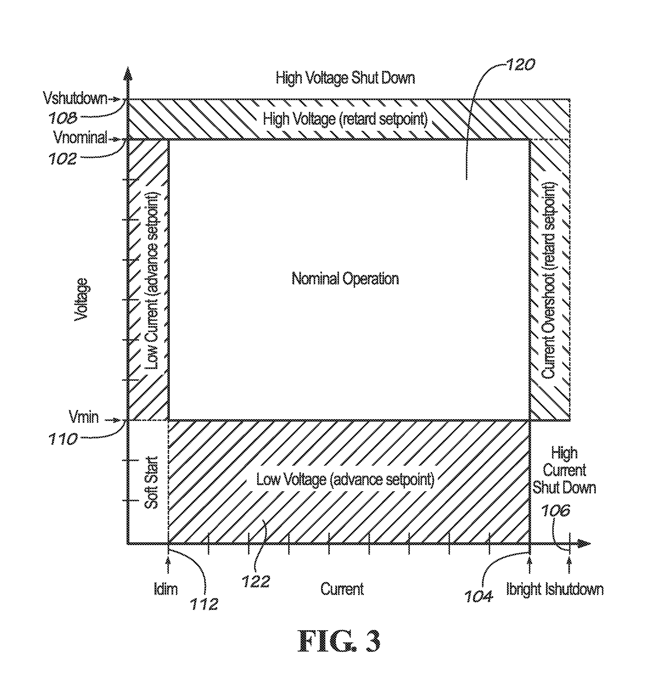
A light fixture includes a driver circuit that fully defines operational characteristics for operation outside of “Nominal Operation” of the driver circuit. The driver circuit increases a target current or set point when the current of the light source (i.e., output current of the driver circuit) or the voltage of the light source (i.e., output voltage of the driver circuit) is below a minimum operating current or minimum operating voltage of the driver circuit regardless of a command current level of the driver circuit. The driver circuit implements a soft start ramp up scheme having a default rate of increase for a set point or target current. After a shutdown, the driver circuit periodically attempts to restart operation by increasing the set point or target current from zero (i.e., shutdown) at a reduced rate as compared to the default rate.

Description

CROSS-REFERENCES TO RELATED APPLICATIONS[0001]This application claims priority to and incorporates by reference in its entirety U.S. Provisional Patent Application Ser. No. 61 / 702,835 entitled “METHOD AND CIRCUIT FOR LED LOAD MANAGEMENT” filed on Sep. 19, 2012.[0002]A portion of the disclosure of this patent document contains material that is subject to copyright protection. The copyright owner has no objection to the reproduction of the patent document or the patent disclosure, as it appears in the U.S. Patent and Trademark Office patent file or records, but otherwise reserves all copyright rights whatsoever.STATEMENT REGARDING FEDERALLY SPONSORED RESEARCH OR DEVELOPMENT[0003]Not ApplicableREFERENCE TO SEQUENCE LISTING OR COMPUTER PROGRAM LISTING APPENDIX[0004]Not ApplicableBACKGROUND OF THE INVENTION[0005]The present invention relates generally to constant current driver circuits. More particularly, this invention pertains to constant current direct current (DC) driver circuits fo...

Claims


Application Information

Patent Timeline
Patent Type & Authority Patents(United States)
IPC IPC(8): H05B37/02H05B44/00
CPCH05B33/0809H05B33/0851H05B45/10H05B45/37H05B45/3725H05B45/14
Inventor MAYS, II, STEPHEN D.DERNOVSEK, JOHN J.
Owner UNIVERSAL LIGHTING TECHNOLOGIES
Why Eureka
Eureka Blog
Learn More