Putter

Inactive Publication Date: 2015-01-13
TAISEI KOGYO CO LTD
View PDF28 Cites 15 Cited by
  • Summary
  • Abstract
  • Description
  • Claims
  • Application Information

AI Technical Summary

Benefits of technology

[0007]The object of the present invention is to provide a putter which allows a golfer to putt a ball accurately to the target by eliminating optical illusion which tends to occur with respect to a target direction of putting.
[0050]And, when lighting and light-collecting function is provided, the golfer can check precisely how a sheet pendulum is in the putter head.

Problems solved by technology

This caused a problem that the golfer could strike the ball for proper distance with ball rolling smoothly, but as a result, the ball arrived at the point deviated to the right from the target, while the golfer who putted the ball did not understand the reason why an intended target line is deviated from the target.

Method used


Image

  • Putter
  • Putter
  • Putter

Examples


Embodiment Construction

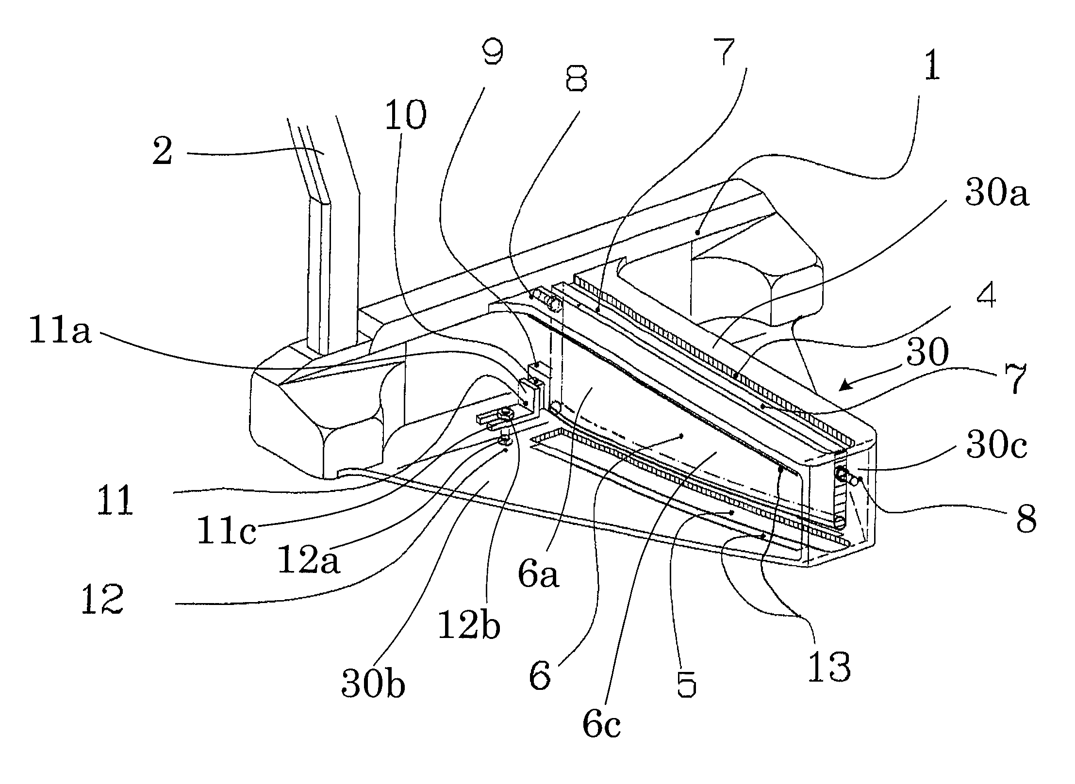
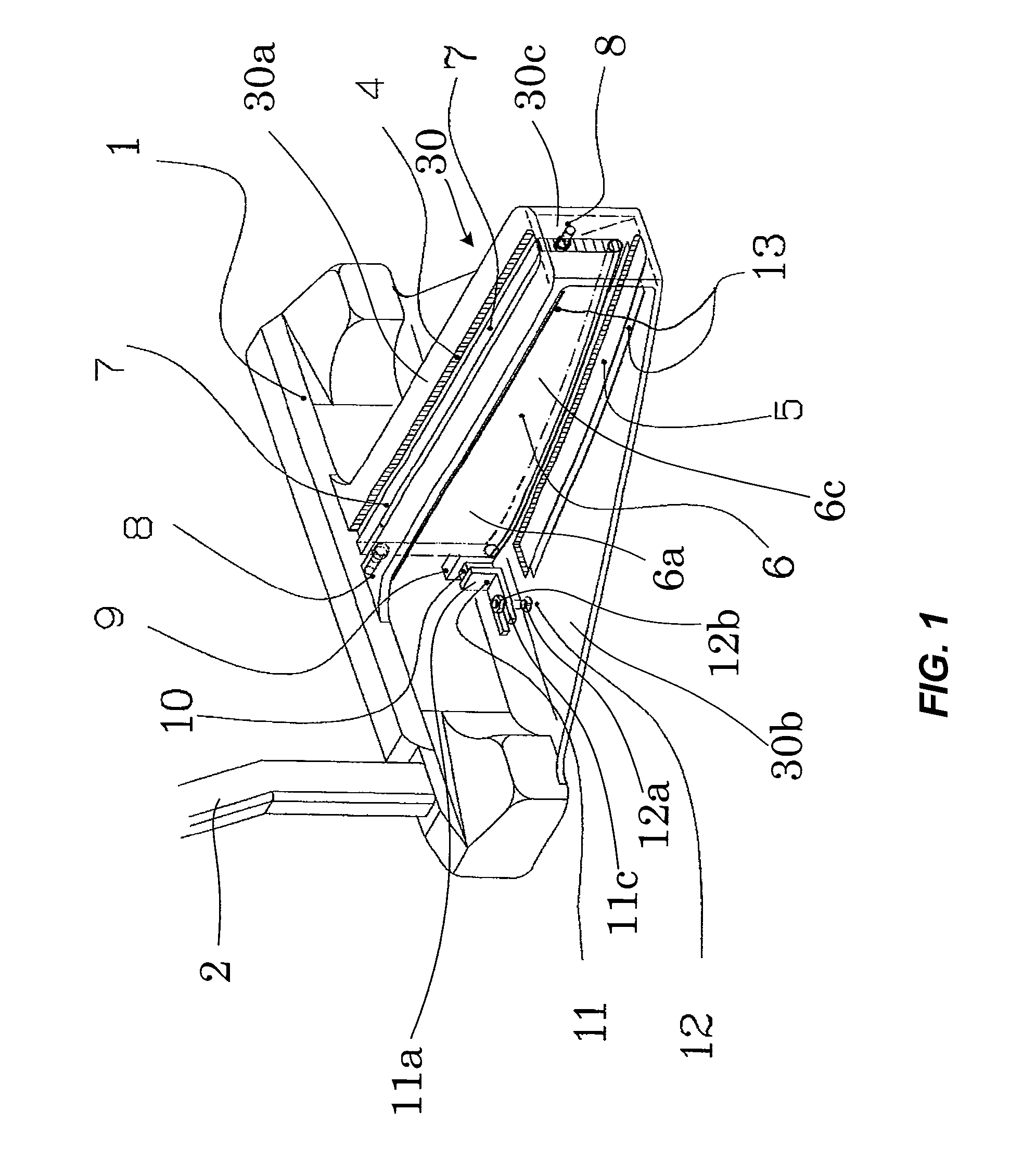
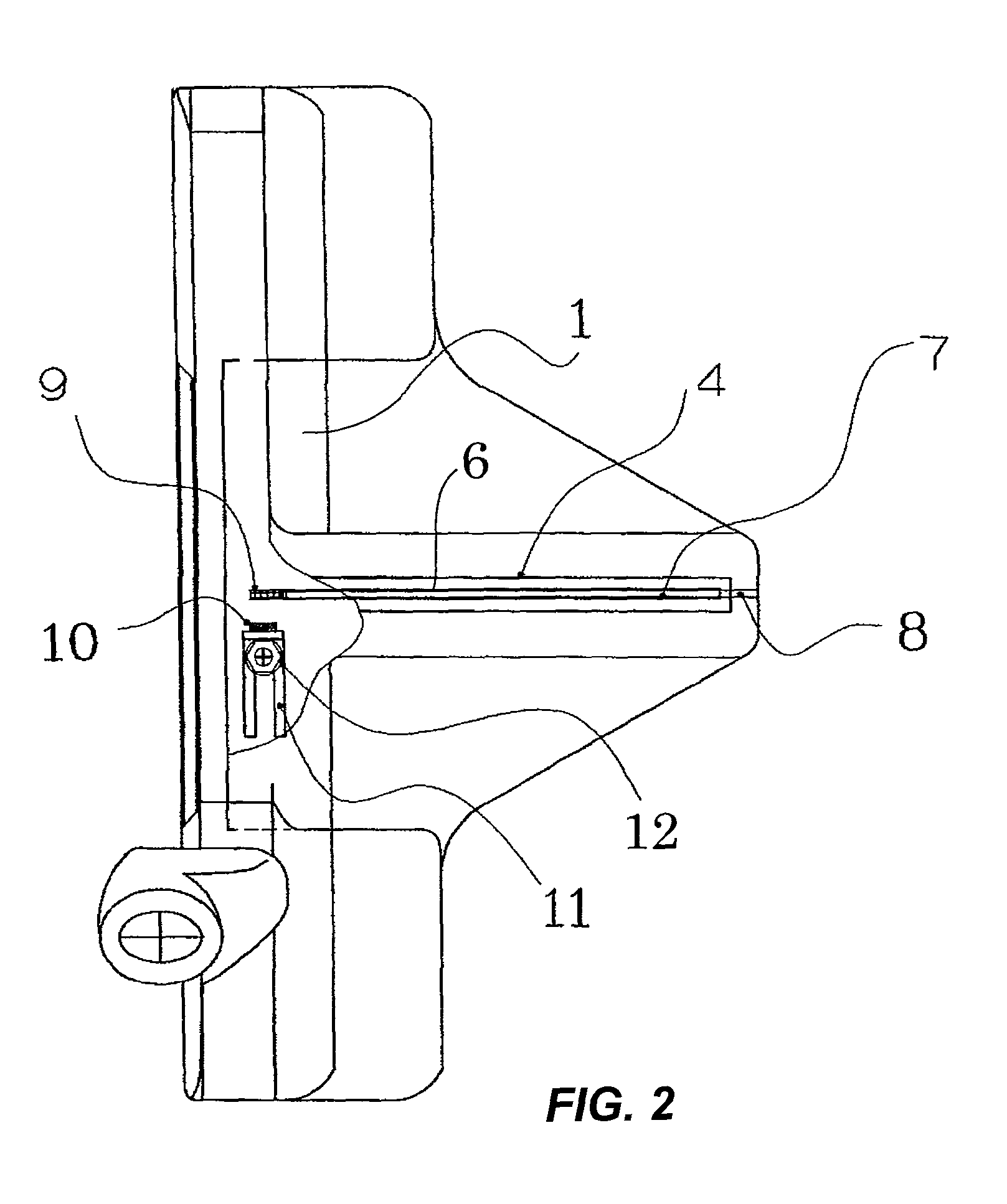
[0071]According to an aspect of the present invention, a putter comprises a putter head 1 made of brass (JIS CAC406), a still shaft 2 of 32 inches (approx. 81 cm) in length attached to the putter head 1 and a rubber grip of 10 inches (approx. 25 cm) in length (not shown). A sheet pendulum body or thin-plate pendulum body 6a is made of aluminum and 0.8 mm in thickness to minimize inertia force at impact. A rotation shaft 8 is made of stainless steel and 0.6 mm in diameter. An iron weight 9 is fixed to the sheet pendulum or thin plate pendulum 6 with iron screws of M1.6 For a hitting surface of the putter head 1, multilayered oil-impregnated metal material is used. A hitting surface member made of the multilayered oil-impregnated metal material is produced as follows. Powders of phosphor-bronze alloy and lead bronze alloy are penetrated to a stainless plate of 2 mm in thickness as a base material by solid-state diffusion to produce porous crystal layers, then polyamide and molybdenum ...


PUM


Abstract

When hitting a ball to a target with a putter, the ball often travels to a point which is deviated to the right from the target. When a golfer looks at the target just after taking his address, he turns his head to a target about a rotation axis which extends through the back of his head. When this rotation axis is not horizontal and an angle defined by the rotation axis and his sighting line to a putter head is not 90°, he has an optical illusion which tricks him into believing that he has to correct his address position. The putter of the present invention is provided with a thin-plate pendulum thereby allowing him to turn his head about the rotation axis while keeping the angle defined by the rotation axis and his sighting line at 90°.

Description

CROSS-REFERENCE TO RELATED APPLICATIONS[0001]This application is a continuation-in-part of International Application No. PCT / JP2010 / 063504, filed on Aug. 9, 2010, which International application was published on Feb. 17, 2011, as International Publication No. WO2011 / 019024 A1 in the Japanese language and which application is incorporated herein by reference. The International application claims priority of Japanese Patent Application No. 2009-185758 filed on Aug. 10, 2009, to which application is incorporated herein by reference.BACKGROUND OF THE INVENTION[0002]The present invention relates to a putter which serves to prevent a golfer from being affected by an optical illusion which tends to occur when the golfer putts a ball to a target.[0003]As means for assisting a golfer hit a straight putt, provided is a putter of which head is provided with a line slot extending through a center of the head and perpendicular to a putting face of the putter, and provided is a putter including a...

Claims


Application Information

Patent Timeline
Patent Type & Authority Patents(United States)
IPC IPC(8): A63B69/36A63B53/04A63B53/06
CPCA63B53/0487A63B53/065A63B2053/0441A63B2209/02A63B53/0441A63B2214/00A63B60/52A63B53/007
Inventor SIMIZU, KIYOSI
Owner TAISEI KOGYO CO LTD
Why Eureka
Try Eureka