Radiation imaging apparatus and phantom used for the same

a technology of imaging apparatus and phantom, which is applied in the field of radiation imaging apparatus, can solve the problems of longitudinal distortion in panoramic images, distortion always occurring in images, and blur in the lateral direction of a reconstructed panoramic image, and achieve the effect of less distortion

Inactive Publication Date: 2013-05-09
TAKARA TELESYST
View PDF2 Cites 25 Cited by
  • Summary
  • Abstract
  • Description
  • Claims
  • Application Information

AI Technical Summary

Benefits of technology

[0022]Accordingly, in the present invention, the structure of an imaging system for each radiation angle of a ration, that is, the three-dimensional structure of the imaging space, is checked accurately through scanning using a phantom. And information indicative of the structure is used provide images of less distortion and of highly accurate reflection of three-dimensional actual positions of objects being imaged.

Problems solved by technology

However, when this positioning condition is not met, distortion always occurs in images.
Further, when a tooth row is not positioned along the referential tomographic plane, there will also be caused blur in the lateral direction of a reconstructed panoramic image.
However, in that case, due to the fact that the longitudinal distortion is not related to the shift & add quantities, there will be left longitudinal distortion in panoramic images.
If there is distortion in an image, a distance between two points in an image cannot be depicted accurately compared with the actual distance.
Obviously, there are various inconveniences, such as, being unable to accurately measure a distance between two points, which result in panoramic images which provide poor measurement capabilities.
Positional changes of this rotation center will cause the enlargement factor in the longitudinal direction of the tooth row to change position by position in a tooth row direction, which results in longitudinal distortion of panoramic images.

Method used


Image

  • Radiation imaging apparatus and phantom used for the same
  • Radiation imaging apparatus and phantom used for the same
  • Radiation imaging apparatus and phantom used for the same

Examples


Embodiment Construction

[0070]With reference to the accompanying drawings, embodiments of the present invention will now be described.

[0071]With reference to FIGS. 1-43, an embodiment of a radiation imaging apparatus and a phantom used by the apparatus, which are according to the present invention, will now be described. In the present embodiment, the radiation imaging apparatus is employed as a dental X-ray panoramic imaging apparatus. The panoramic imaging apparatus will now be detailed.

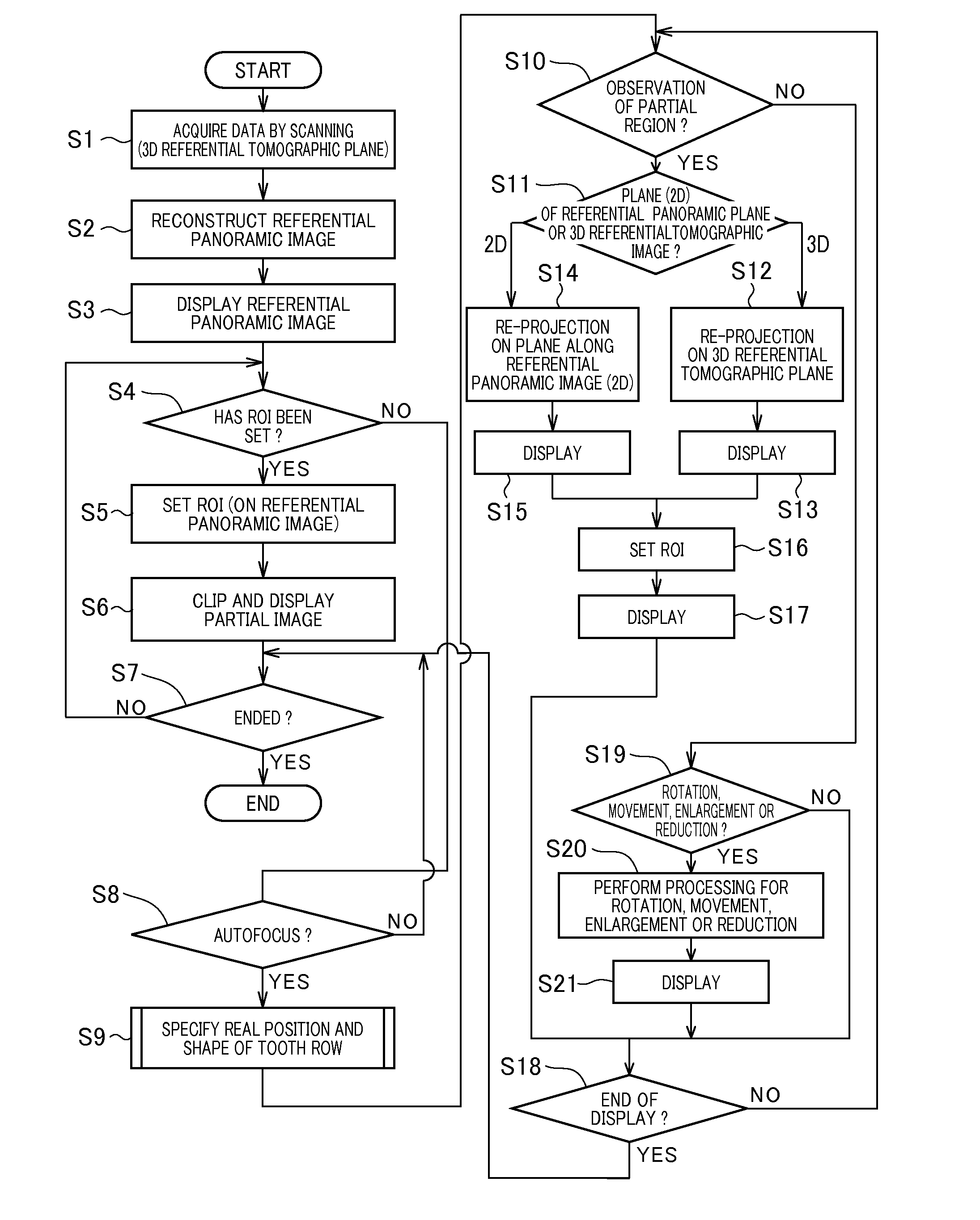
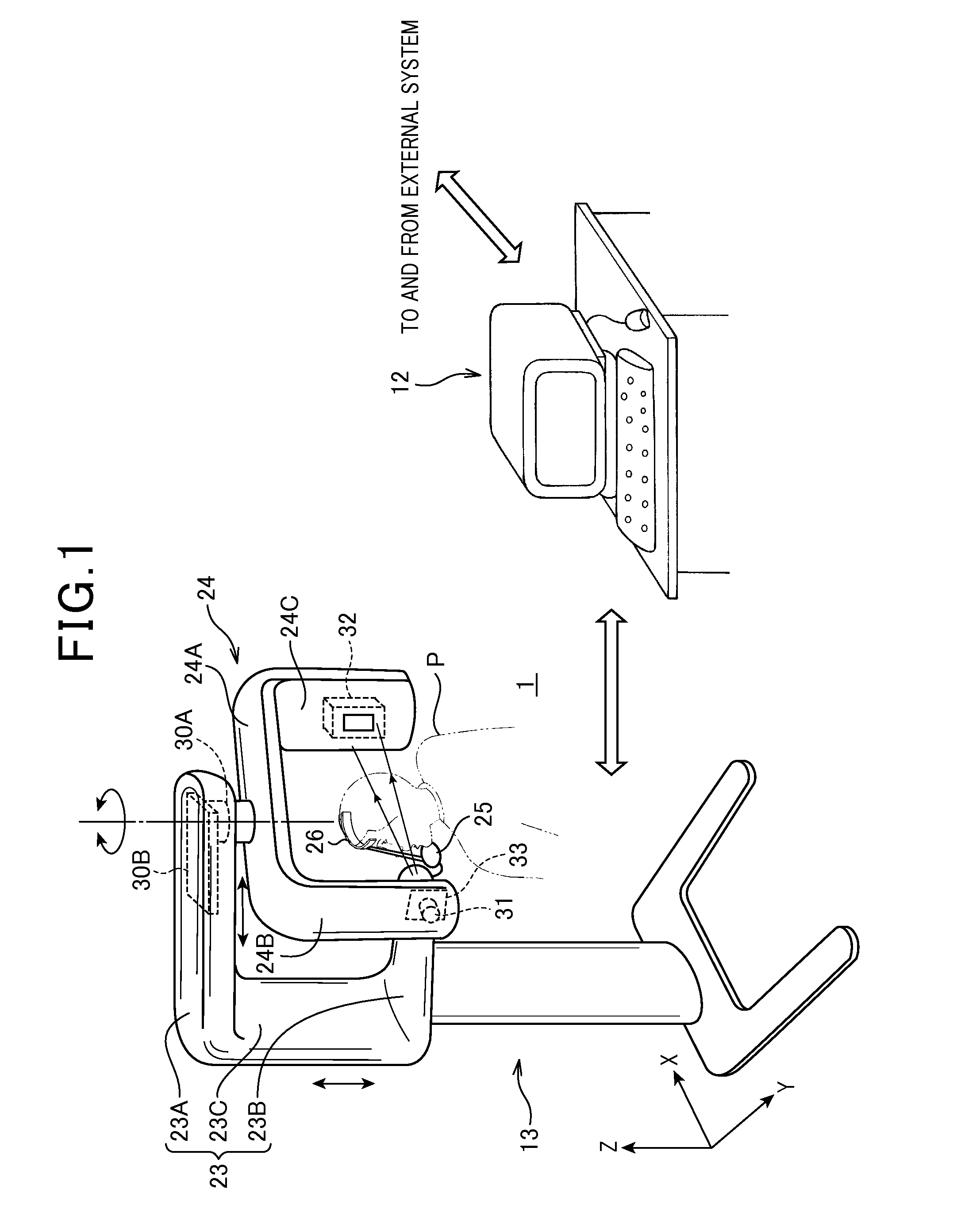
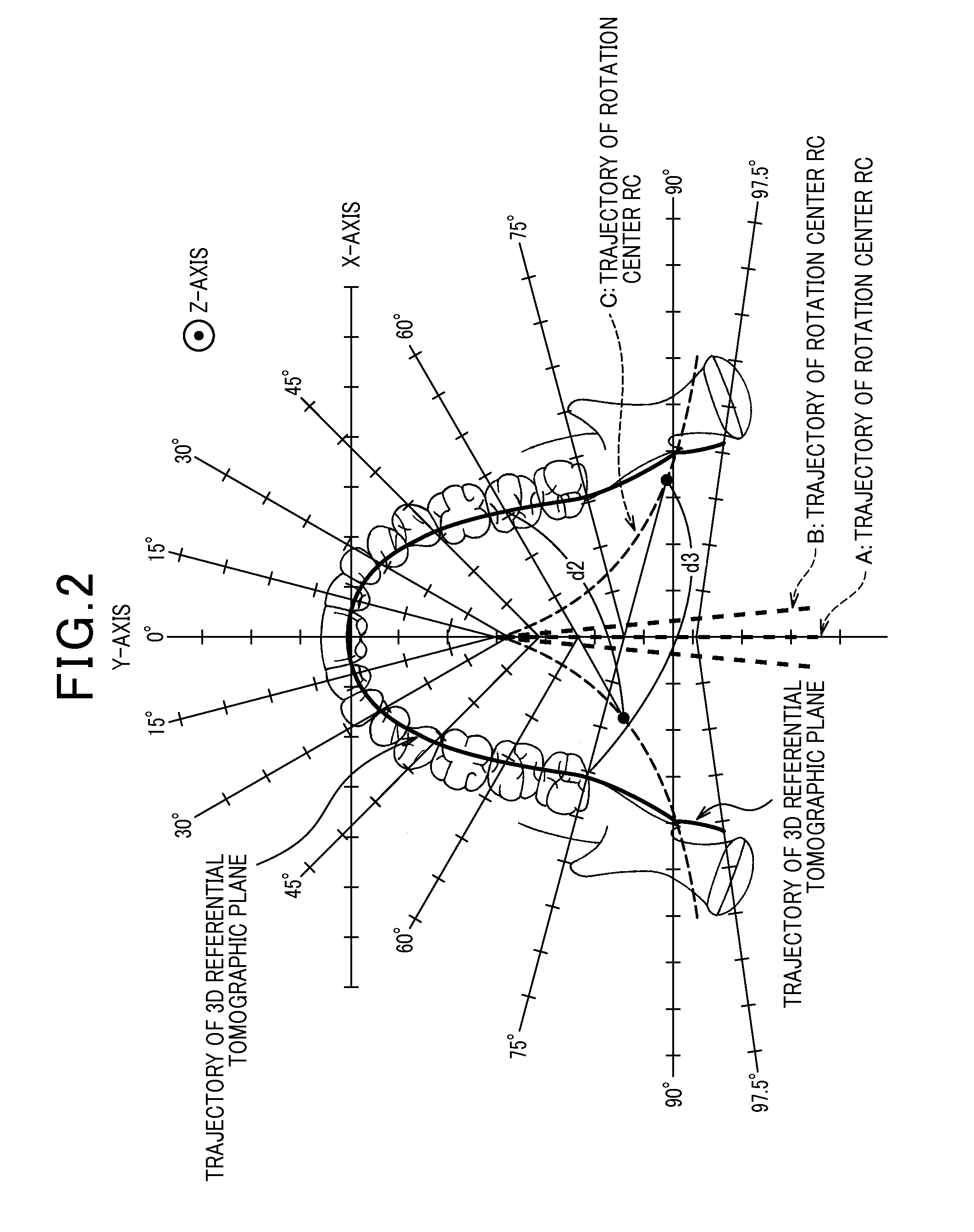
[0072]FIG. 1 outlines the appearance of the panoramic imaging apparatus 1. This panoramic imaging apparatus 1 is able to scan, with an X-ray beam, the jaw of an object to obtain digital-quantity X-ray transmission data, and use the data to specify an actual three-dimensional real position (i.e., actually-existence position) of the tooth row and to produce (or reconstruct) panoramic images of the tooth row, whose irregularities (or differences) caused due to longitudinal enlargement factors are compensated based on a tomos...


PUM


Abstract

In the imaging space provided by a panoramic imaging apparatus, a phantom is arranged. The phantom is located to a predetermined tomographic plane and includes markers which image known positional information with an X-ray beam. The X-ray beam from an X-ray source is acquired as X-ray transmission data by a detector, and a panoramic image is produced using the data. Based on known positional information of the markers and information of marker positions in the panoramic image, distance information (Rs, Rd) between the X-ray tube and the detector and height information (B1) of the X-ray tube to the detector are calculated. From this calculated results and the acquired data, parameters (Δx/ΔFi, θ, Δθ/ΔFi, D, A, CX, CY) defining positional relationships among the X-ray tube, the detector, and the tomographic plane are calculated such that amounts of changes in the position connecting the X-ray tube and the detector are considered in the parameters. This allows the parameters to be calibrated for 3D image reconstruction.

Description

FIELD OF THE INVENTION[0001]The present invention relates to a radiation imaging apparatus that images an object using radiation and a phantom used in the apparatus, and in particular, to a radiation imaging apparatus that produces images such as panoramic images of an object according to a tomosynthesis technique and the phantom used by the apparatus for calibration thereof and a structural analysis of the imaging space provided by the apparatus.BACKGROUND ART[0002]In recent years, tomographic imaging using a tomosynthesis technique has been used actively. The theory of this tomosynthesis technique has been known long before (for example, refer to patent document 1), and recently, tomographic imaging that enjoys ease of image reconstruction performed using the tomosynthesis technique has been proposed (for example, refer to patent documents 2 and 3). Especially, many such cases can be found in dental and mammographic fields (for example, refer to patent documents 4, 5 and 6).[0003]...

Claims


Application Information

Patent Timeline
Patent Type & Authority Applications(United States)
IPC IPC(8): A61N5/10
CPCA61B6/14A61B6/547A61B6/583A61B6/588A61N5/1075G06T2211/436A61B6/027A61B6/469G06T11/006A61B6/025A61B6/0492A61B6/4452A61B6/584A61B6/03
Inventor YAMAKAWA, TSUTOMUOGAWA, KOICHIKATSUMATA, AKITOSHITSUJITA, MASAHIRONAGAOKA, HIDEYUKI
Owner TAKARA TELESYST
Why Eureka
Try Eureka