System for communication of video, audio, data, control or other signals over fiber

a fiber optic and fiber optic technology, applied in the field of communication systems, can solve the problems of large cost, large cable size and weight, noise or distortion, etc., and achieve the effect of little or no overhead

Active Publication Date: 2009-01-06
MULTIDYNE ELECTRONICS
View PDF10 Cites 46 Cited by
  • Summary
  • Abstract
  • Description
  • Claims
  • Application Information

AI Technical Summary

Benefits of technology

[0012]More specifically, the illustrative embodiment provides a high-speed serial digital communication and control system, and corresponding methods of operation, suitable for use in surveillance, broadcast or other applications. This embodiment allows real-time control of cameras or other input / output devices. The digital transmission of video, audio and data has more noise immunity and less distortion than conventional analog systems. Since this embodiment does not compress the digitized video, there are no motion artifacts or loss of image quality. The illustrative embodiment uses fiber optic cables which allow for an increase in the distance between remote units and the hub or base units, allows for easy mixing of different camera types, and provides the option of system expansion by adding additional remote interfaces and corresponding video sources. The present invention allows the simultaneous transport of a plurality of remote video sources.
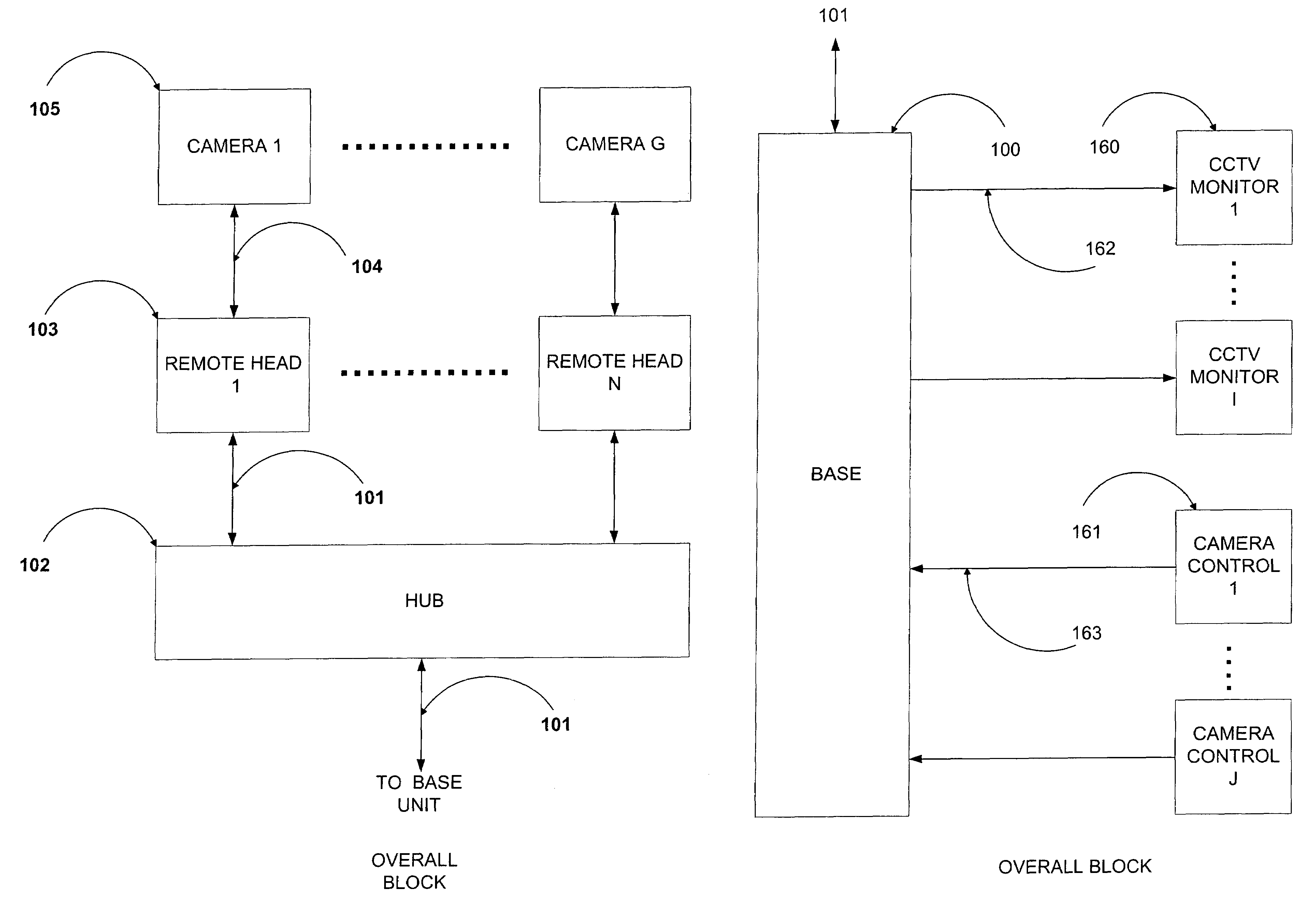
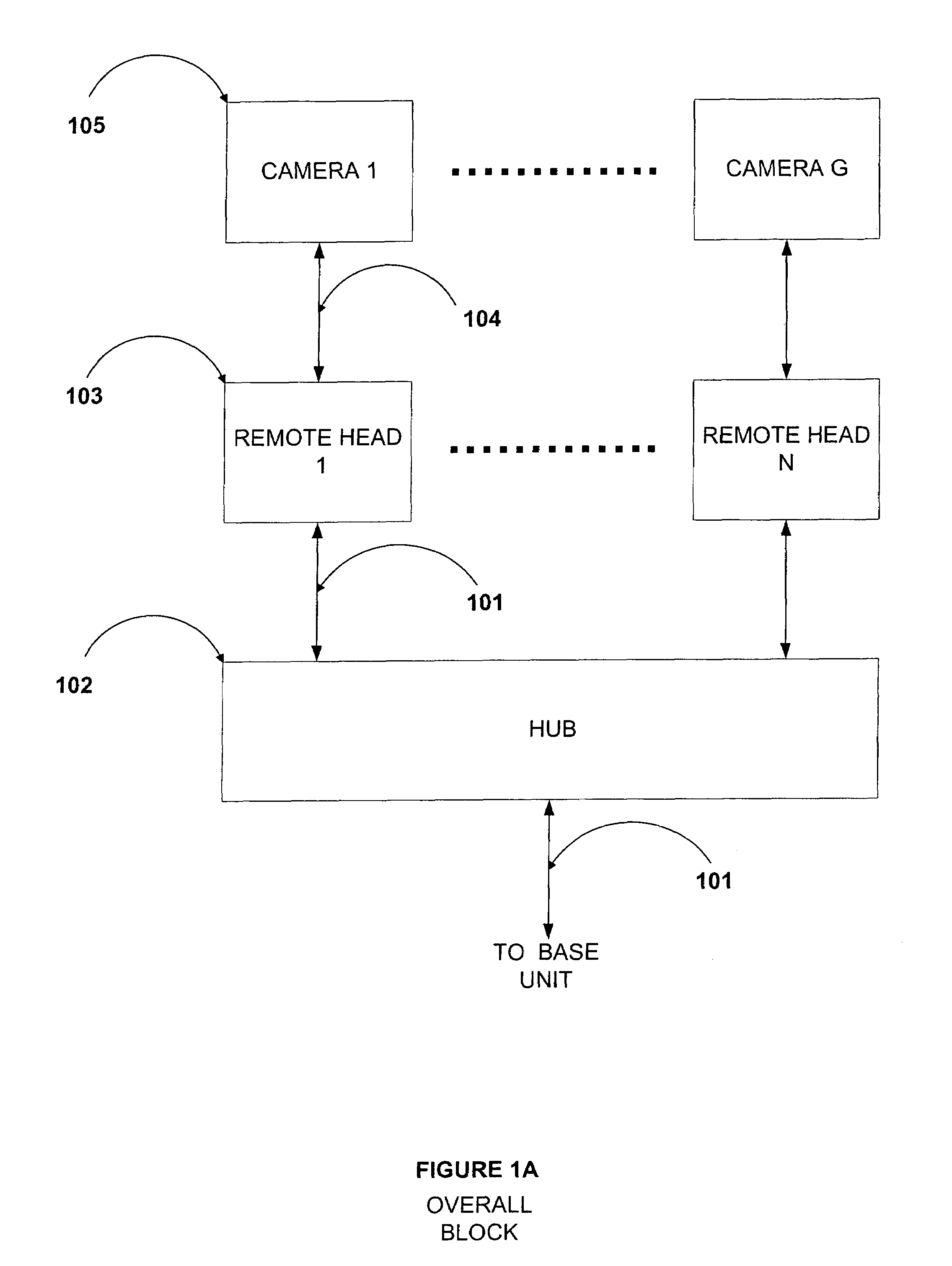
[0014]Each remote interface unit accepts and converts analog video and audio signals into digital downlink data for transmission over its own fiber optic cable to the central hub unit. This remote interface also accepts digital data signals, if present, from its remote source, or an end user there, and combines these with the digital downlink stream that includes the above video. These data signals could also include status information, such as video present or uplink fail. Each remote head also receives, over the same fiber optic cable, digital uplink data and control signals from the hub which originated from the base, selects the data and / or control signals that are assigned to it, and outputs these to control the remote source and / or convey data to an end user there. Each remote head also has a programmable cable equalizer circuit, to compensate for long coaxial cable runs from the analog video source to the remote head. In this way, high frequency roll-off due to cable losses can be compensated for. The equalizer can be bypassed for short cable distances.
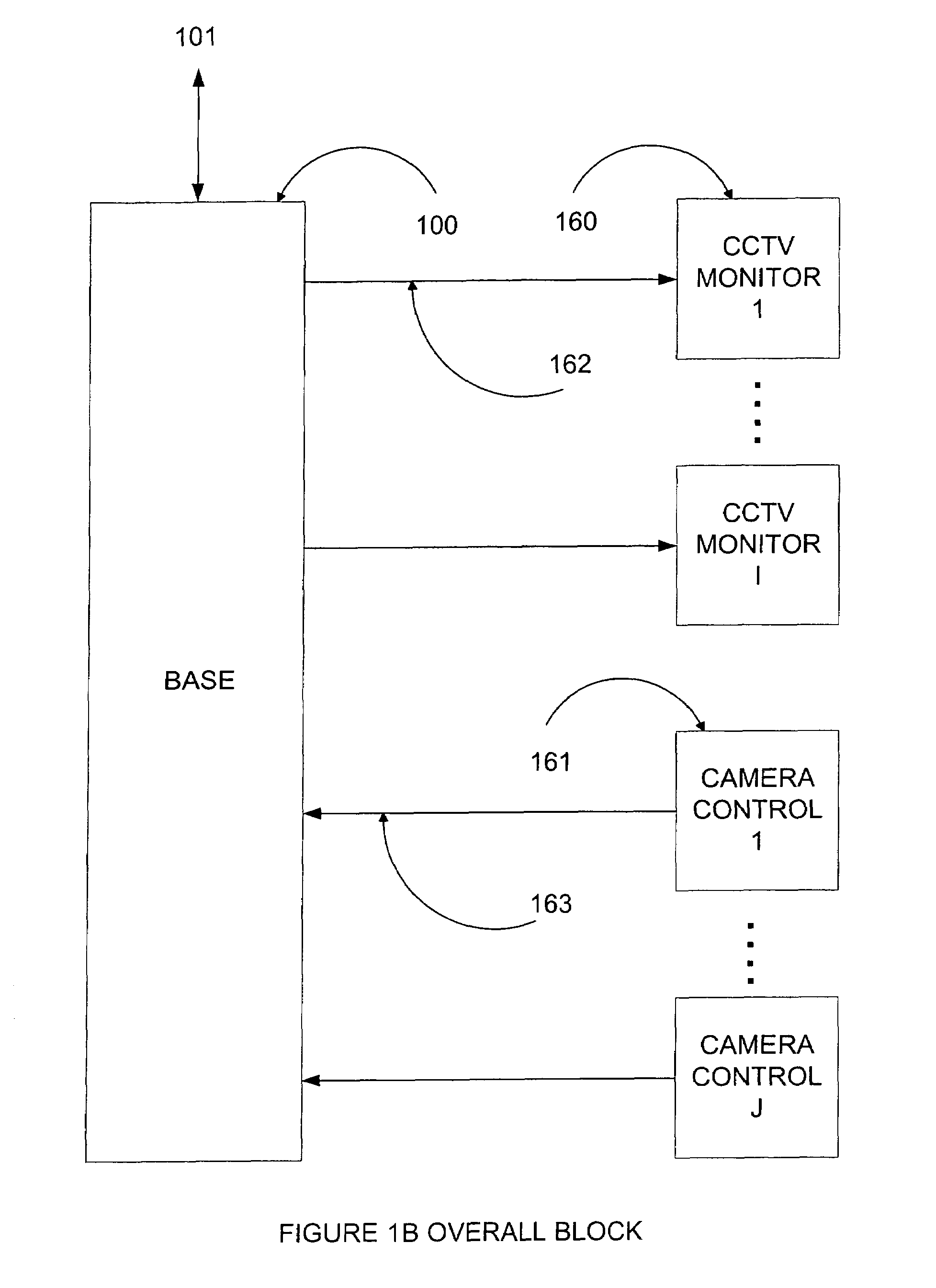
[0017]In addition to the combined data and control signals that are destined for the individual remote heads, the uplink stream from the base also has embedded within it, a master clock signal derived from a master clock source in the base. This is used to reconstruct a replica of the master clock in the hub and each remote head, so that all clocks throughout the system are frequency locked, and any videos that are digitized at the heads can be combined digitally at the hub and streamed to the base without the above-noted problems associated with clock frequency differences. There will still be a phase difference between the recovered clock in the hub and the clock associated with the data from any one remote head, due to path lengths from the head to the hub, but this can be accommodated by a very small, inexpensive FIFO memory which cannot underflow or overflow, in the manner described previously, because the input and output clock frequencies are now the same. Thus, the video can be kept in digital format and transported and recovered with little or no overhead because the system is completely synchronous.
[0018]The uplink stream also has embedded within it, reference signals that enable each remote head, and the hub, to locate within the stream the uplink data and control signals destined for it. In this way each head can be accessed individually and simultaneously. Each head can be programmed to capture data and / or control from any one of the interfaces at the base. The streams uplinked from the base to the hub, and from the hub to the heads are all identical (i.e., they are the same signal). This has the advantage of allowing an individual head to be moved from port to port on the hub without having to reprogram that head, unlike other systems, which may assign a remote head to one hub port only.
[0021]The system can handle control protocols for a multiplicity of camera types, because it is transparent to them. Unlike other systems, the system in the illustrative embodiment does not require a microcontroller or any other form of software, firmware or intelligence to manage user data or prior knowledge of the protocol of that data in order to packetize it or to add signal management content to it, such as address bits, data type bits, start and stop bits, so that it can be routed to, and extracted by, a specific location. The time-division multiplexing of the raw user data and the broadcast nature of the uplink and downlink multiplexed data combined with a reference signal for time-division demultiplexing and extraction of data by the intended destination, ensures a simple, low cost, transparent means of data communication. It will be apparent to anyone skilled in the art that, except for the bit-error rate testing and system health monitoring functions, the illustrative embodiment may be implemented as a completely “hardware-based” system, although numerous other implementations are possible using various combinations of hardware, software or firmware.

Problems solved by technology

Connecting the sources to the multiplexer via coaxial or twisted-pair cable has other disadvantages, such as the size and weight of the cable, or problems arising from having a direct electrical connection between source and multiplexer.
One may try to circumvent these problems, if long distances or electrical isolation are required, by using a fiber optic link to connect the video source to the multiplexer, but this link would either have to be analog intensity or FM modulated, which can introduce noise or distortion, or convert the video to digital form and then back to analog again, for input to the multiplexer, which is expensive and involves extra conversion processes which can also introduce noise or distortions.
But it can add greatly to the cost.
This repeating or dropping of frames can cause motion artifacts in the video image.
A smaller, less expensive FIFO cannot be used because underflow or overflow would occur more rapidly, and would necessitate the dropping or repeating of individual pixels within a video frame, which would be more visually upsetting to the user, and cause a loss of synchronization in the video monitor, because the length of the video frame would be altered by the repetition or dropping of pixels.
This adds overhead in the form of increased bandwidth requirements for the communications link, complexity and cost.
The increased bandwidth requirements can be addressed by resorting to video compression, but this can result in loss of quality, which can be in the form of motion artifacts or loss of fine detail in the image.
This can be a disadvantage in a surveillance system when one is trying to capture an image such as a face or a license plate number.
There is also the increased cost resulting from the compression and decompression circuitry.
Conventional surveillance or broadcast fiber optic video links also lack a built-in video test signal generator with multiple patterns at the source for performance verification and various system alignment tasks.
This is insufficient for all the tests that might need to be performed on the system.
Current systems also exhibit significant latency between the video image and the camera pan, tilt and zoom controls.
Due to the latency, the user has difficulty controlling the pan, tilt and zoom functions of the camera system.
The user executes a command to move a camera, but the system exhibits significant delay before movement is preserved on the video monitor.
The latency causes the user to overcompensate all camera movements.

Method used


Image

  • System for communication of video, audio, data, control or other signals over fiber
  • System for communication of video, audio, data, control or other signals over fiber
  • System for communication of video, audio, data, control or other signals over fiber

Examples


Embodiment Construction

[0041]The present invention in an illustrative embodiment to be described below provides a system for multiplexing and digital transmission of signals from remote video sources, such as cameras, bidirectional audio, and for bidirectional digital serial communication and control of these remote sources, such as camera pan / tilt / zoom, over fiber optic cable, for surveillance, broadcast television, or other applications. It is to be appreciated, however, that the invention can be implemented in a wide variety of other system configurations, in order to meet the particular needs of a given application.

[0042]The system can be configured as multiple remote video interfaces, which connect each camera or other video source, via a single fiber optic cable, over a distance of many kilometers (e.g., up to 20 kilometers or more), to a central hub. Up to N remote interfaces can be accommodated, where N and other variables referred to herein are arbitrary numbers that can take on any desired value...


PUM


Abstract

A system for communication of signals between remote devices and monitoring and control devices via fiber. The system in accordance with one aspect of the invention includes a plurality of remote interface units each coupled to a corresponding one of the remote devices, a base unit coupled to one or more monitoring devices and one or more control devices, and a central hub coupled between the base unit and the plurality of remote interface units. The central hub is coupled to the base unit by a first fiber optic link, and is coupled to the remote interface units by additional fiber optic links.

Description

CROSS-REFERENCE TO RELATED APPLICATION(S)[0001]The present application claims the priority of U.S. provisional application Ser. No. 60 / 544,140, filed Feb. 12, 2004.FIELD OF THE INVENTION[0002]The present invention relates generally to communication systems, and more particularly to surveillance or broadcast video systems, or other types of systems for communicating video, audio, data, control or other signals over fiber.BACKGROUND OF THE INVENTION[0003]In conventional surveillance and broadcast video systems, where many analog video sources are required to be combined or multiplexed for transmission over a single link, whether it be fiber or copper cable, the video inputs to the combining device typically have to be in analog form. The conversion from analog to digital is done inside the combining device, where the analog to digital converters can each be clocked by the same clock edge. This is shown in FIGS. 1C and 1D.[0004]It will be evident to one skilled in the art that in order...

Claims


Application Information

Patent Timeline
Patent Type & Authority Patents(United States)
IPC IPC(8): H04B10/08H04B17/00
CPCH04N7/181H04N7/22
Inventor JACHETTA, VINCENTMOORE, BRIAN C.JACHETTA, JAMES G.JACHETTA, FRANCIS P.
Owner MULTIDYNE ELECTRONICS
Why Eureka
Try Eureka