
System for communication of video, audio, data, control or other signals over fiber

a fiber optic and fiber optic technology, applied in the field of communication systems, can solve the problems of large cost, large cable size and weight, noise or distortion, etc., and achieve the effect of little or no overhead

Active Publication Date: 2011-04-05
MULTIDYNE ELECTRONICS
View PDF18 Cites 3 Cited by
  • Summary
  • Abstract
  • Description
  • Claims
  • Application Information

AI Technical Summary

Benefits of technology

The system provides noise-immune, high-quality transmission of multiple video streams over long distances with reduced latency and complexity, enabling efficient control and testing of remote devices, and supports simultaneous transport of multiple video sources without compression, thus enhancing surveillance and broadcast applications.

Problems solved by technology

Connecting the sources to the multiplexer via coaxial or twisted-pair cable has other disadvantages, such as the size and weight of the cable, or problems arising from having a direct electrical connection between source and multiplexer.
One may try to circumvent these problems, if long distances or electrical isolation are required, by using a fiber optic link to connect the video source to the multiplexer, but this link would either have to be analog intensity or FM modulated, which can introduce noise or distortion, or convert the video to digital form and then back to analog again, for input to the multiplexer, which is expensive and involves extra conversion processes which can also introduce noise or distortions.
But it can add greatly to the cost.
This repeating or dropping of frames can cause motion artifacts in the video image.
A smaller, less expensive FIFO cannot be used because underflow or overflow would occur more rapidly, and would necessitate the dropping or repeating of individual pixels within a video frame, which would be more visually upsetting to the user, and cause a loss of synchronization in the video monitor, because the length of the video frame would be altered by the repetition or dropping of pixels.
This adds overhead in the form of increased bandwidth requirements for the communications link, complexity and cost.
The increased bandwidth requirements can be addressed by resorting to video compression, but this can result in loss of quality, which can be in the form of motion artifacts or loss of fine detail in the image.
This can be a disadvantage in a surveillance system when one is trying to capture an image such as a face or a license plate number.
There is also the increased cost resulting from the compression and decompression circuitry.
Conventional surveillance or broadcast fiber optic video links also lack a built-in video test signal generator with multiple patterns at the source for performance verification and various system alignment tasks.
This is insufficient for all the tests that might need to be performed on the system.
Current systems also exhibit significant latency between the video image and the camera pan, tilt and zoom controls.
Due to the latency, the user has difficulty controlling the pan, tilt and zoom functions of the camera system.
The user executes a command to move a camera, but the system exhibits significant delay before movement is preserved on the video monitor.
The latency causes the user to overcompensate all camera movements.

Method used


Image

  • System for communication of video, audio, data, control or other signals over fiber
  • System for communication of video, audio, data, control or other signals over fiber
  • System for communication of video, audio, data, control or other signals over fiber

Examples


Embodiment Construction

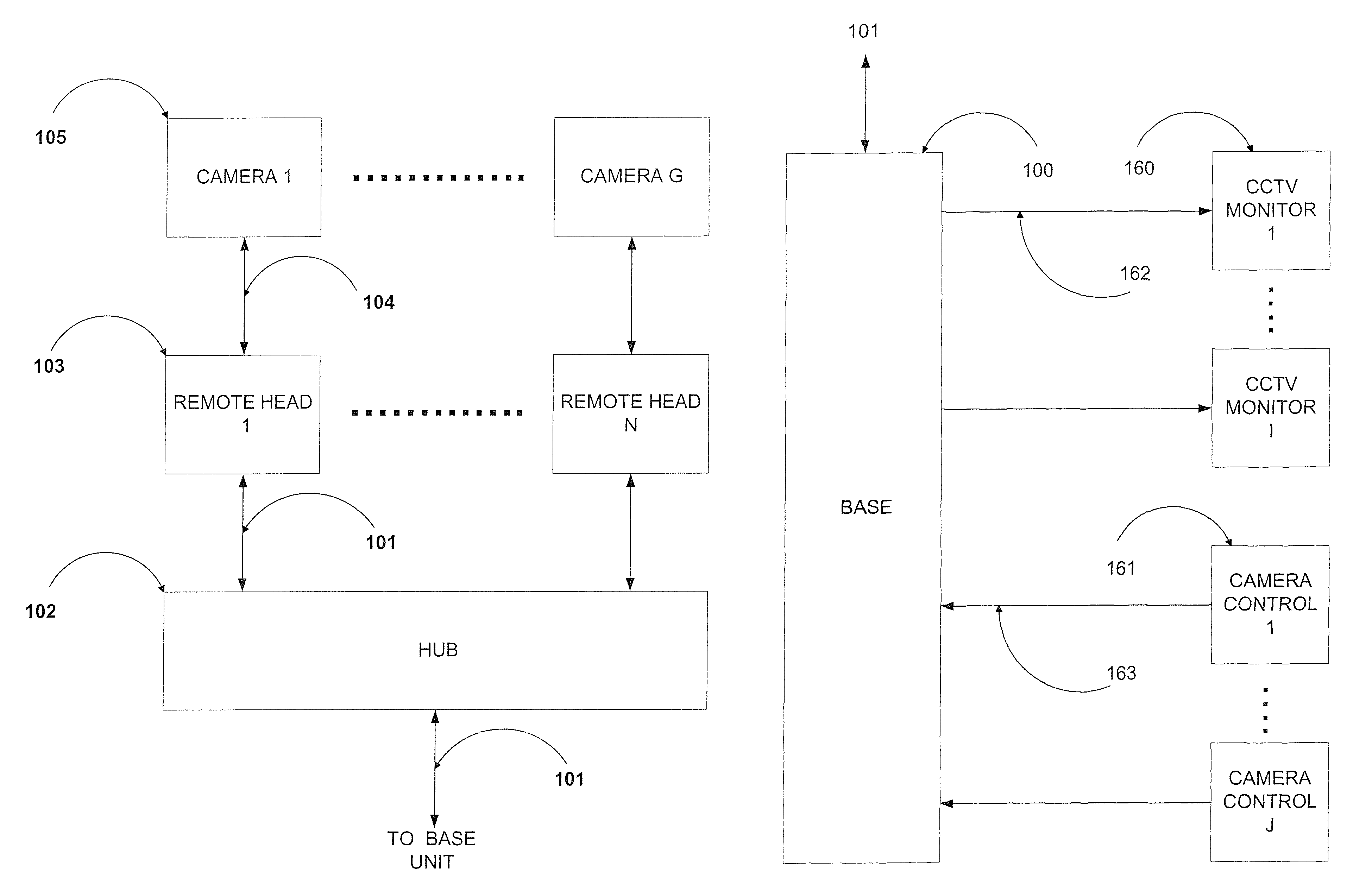
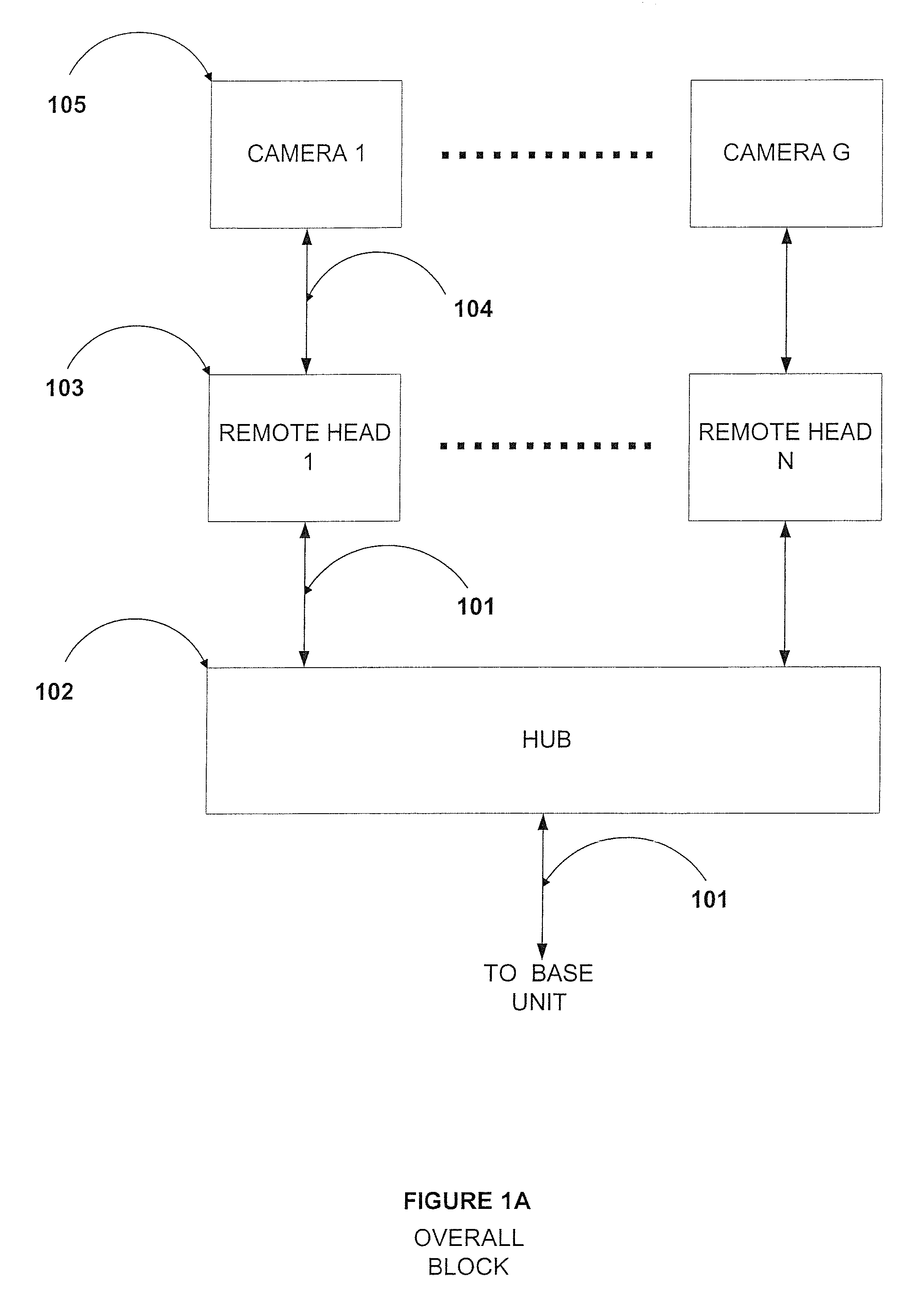
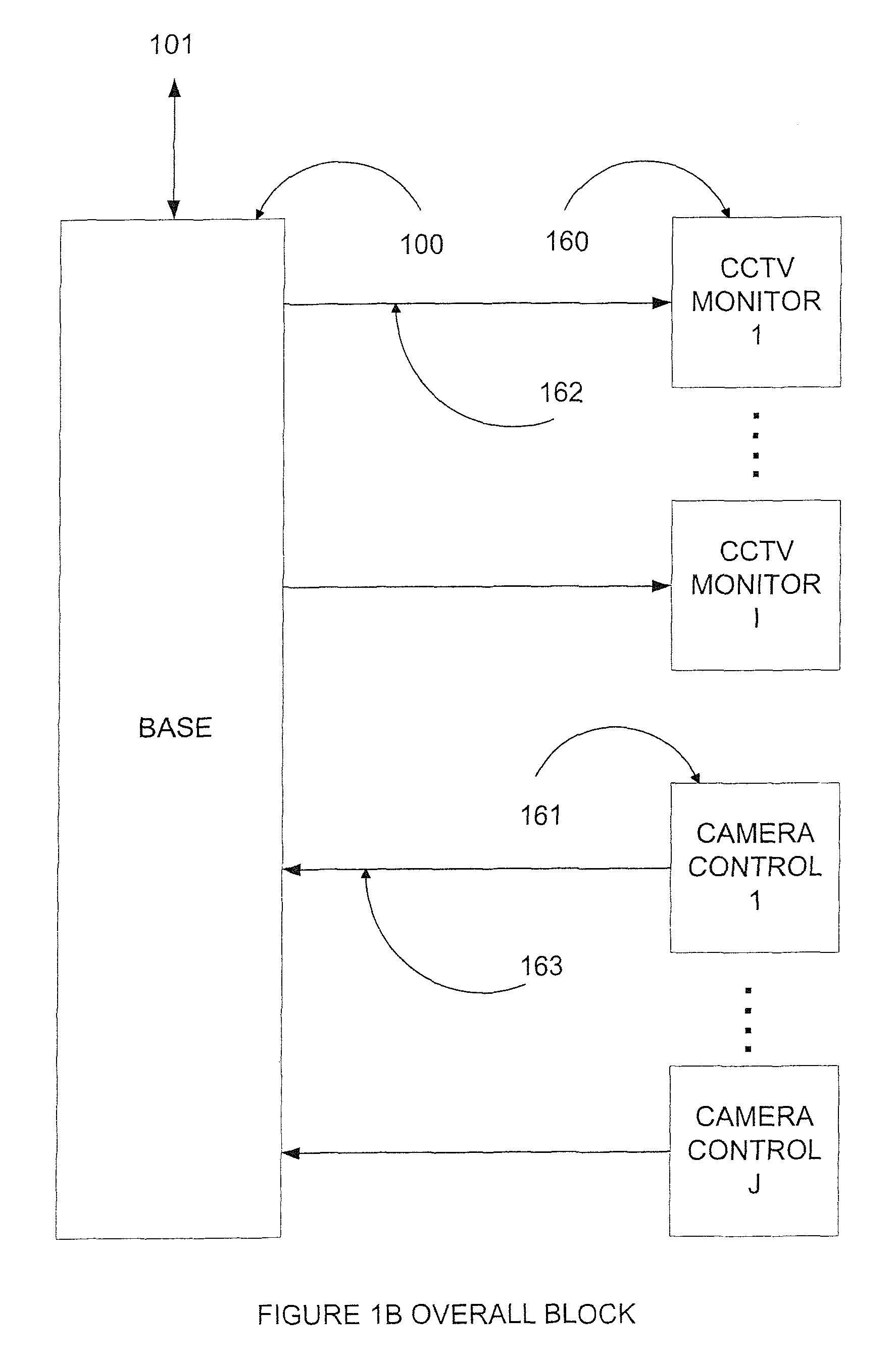
[0041]The present invention in an illustrative embodiment to be described below provides a system for multiplexing and digital transmission of signals from remote video sources, such as cameras, bidirectional audio, and for bidirectional digital serial communication and control of these remote sources, such as camera pan / tilt / zoom, over fiber optic cable, for surveillance, broadcast television, or other applications. It is to be appreciated, however, that the invention can be implemented in a wide variety of other system configurations, in order to meet the particular needs of a given application.

[0042]The system can be configured as multiple remote video interfaces, which connect each camera or other video source, via a single fiber optic cable, over a distance of many kilometers (e.g., up to 20 kilometers or more), to a central hub. Up to N remote interfaces can be accommodated, where N and other variables referred to herein are arbitrary numbers that can take on any desired value...


PUM


Abstract

A system for communication of signals between remote devices and monitoring and control devices via fiber. The system in accordance with one aspect of the invention includes a plurality of remote interface units each coupled to a corresponding one of the remote devices, a base unit coupled to one or more monitoring devices and one or more control devices, and a central hub coupled between the base unit and the plurality of remote interface units. The central hub is coupled to the base unit by a first fiber optic link, and is coupled to the remote interface units by additional fiber optic links.

Description

CROSS-REFERENCE TO RELATED APPLICATION(S)[0001]This application is a continuation of U.S. application Ser. No. 11 / 056,466 filed on Feb. 11, 2005, the disclosure of which is incorporated herein by reference. U.S. application Ser. No. 11 / 056,466 claims the priority of U.S. Provisional Application Ser. No. 60 / 544,140, filed on Feb. 12, 2004, the disclosure of which is incorporated by reference herein.FIELD OF THE INVENTION[0002]The present invention relates generally to communication systems, and more particularly to surveillance or broadcast video systems, or other types of systems for communicating video, audio, data, control or other signals over fiber.BACKGROUND OF THE INVENTION[0003]In conventional surveillance and broadcast video systems, where many analog video sources are required to be combined or multiplexed for transmission over a single link, whether it be fiber or copper cable, the video inputs to the combining device typically have to be in analog form. The conversion fro...

Claims


Application Information

Patent Timeline
Patent Type & Authority Patents(United States)
IPC IPC(8): H04B10/08
CPCH04N7/22H04N7/181
Inventor JACHETTA, VINCENTMOORE, BRIAN C.JACHETTA, JAMES G.JACHETTA, FRANCIS P.
Owner MULTIDYNE ELECTRONICS
Learn More