HAND-HELD MICROWAVE SPECTRUM ANALYZER WITH OPERATION RANGE FROM 9 KHz TO OVER 20 GHz

a spectrum analyzer and hand-held technology, applied in the direction of instruments, noise figure or signal-to-noise ratio measurement, waveguide type devices, etc., can solve the problems of inability to meet the requirements of a handheld device, the external frequency converter's value can exceed the value of the spectrum analyzer, and the measurement performance or cost is unacceptable, so as to enhance the compatibility of mmic and the pcb, improve the switch performance, and increase the cost of components

Active Publication Date: 2009-06-25
ANRITSU CO
View PDF9 Cites 41 Cited by
  • Summary
  • Abstract
  • Description
  • Claims
  • Application Information

AI Technical Summary

Benefits of technology

[0012]The baseband path initially provides a pre-amplifier for signals below approximately 4 GHz. Low-cost components are available for the pre-amplifier at this frequency, while at frequencies above 4 GHz in the baseband and highband paths, no pre-amplifier is used since it would require more costly components. To provide broadband termination of the 1st mixer IF port, the baseband path incorporates a new quadrature-coupled directional (QCD) filter that incorporates a ring resonator to provide a narrow passband. Further, an inexpensive air dielectric multi-cavity bandpass filter is used to pass a 1st mixer IF signal to the 2nd mixer input while suppressing signals at the 2nd mixer image frequency. The air dielectric 1st IF filter operates at higher frequencies than would be practical for ceramic filters commonly used in this type of application.
[0013]The highband path is broken into highband and midband paths. In the midband path, multi-throw MMIC PIN diode switches are used to direct the signal through a bank of bandpass filters to selectively filter different bands of signals. The PIN diode MMIC dice are integrated into surface-mount packages that enhance MMIC compatibility with the PCB and improve switch performance. The highband, midband and baseband signals are downconverted using three separate 1st mixers, such that the midband and highband paths each operate over an octave of frequency.
[0014]A 1st LO signal is created that is selectively provided by a multi-way switch to the 1st mixer of each of the baseband, midband and highband. The 1st LO oscillator frequency is controlled and stabilized by a phase lock loop (PLL) circuit. The PLL incorporates a divide-by-two frequency divider in conjunction with a frequency sampler in the feedback path from VCO to a phase detector. The inclusion of a frequency divider between the VCO and sampler enables the use of a low-cost sampler that has been optimized for lower frequencies to serve with a higher frequency VCO. The output of the 1st LO is frequency doubled to provide a signal to the highband 1st mixer to extend the frequency range of the highband path significantly, while a selectable filter reduces the spurious subharmonics that result from the frequency doubling.

Problems solved by technology

But adding the external frequency converter may create a device that is no longer handheld.
Further, to preserve measurement accuracy the cost of the external frequency converter can exceed the value of the spectrum analyzer.
The upper frequency limit of previous handheld spectrum analyzers was constrained largely by the perception that achievement of higher frequency capability would result in unacceptable measurement performance or cost.
The selection of inexpensive surface-mount (SMT) switches, amplifiers, mixers, and other elements used to construct current low-cost small size spectrum analyzers has been limited for designs operating at frequencies greater than 6 GHz.
A simple extension of prior-art designs using these circuit elements would result in a spectrum analyzer with excessive input noise, signal distortion, and susceptibility to damage from large signals and electrostatic discharge.
Low-cost components are available for the pre-amplifier at this frequency, while at frequencies above 4 GHz in the baseband and highband paths, no pre-amplifier is used since it would require more costly components.

Method used


Image

  • HAND-HELD MICROWAVE SPECTRUM ANALYZER WITH OPERATION RANGE FROM 9 KHz TO OVER 20 GHz
  • HAND-HELD MICROWAVE SPECTRUM ANALYZER WITH OPERATION RANGE FROM 9 KHz TO OVER 20 GHz
  • HAND-HELD MICROWAVE SPECTRUM ANALYZER WITH OPERATION RANGE FROM 9 KHz TO OVER 20 GHz

Examples


Embodiment Construction

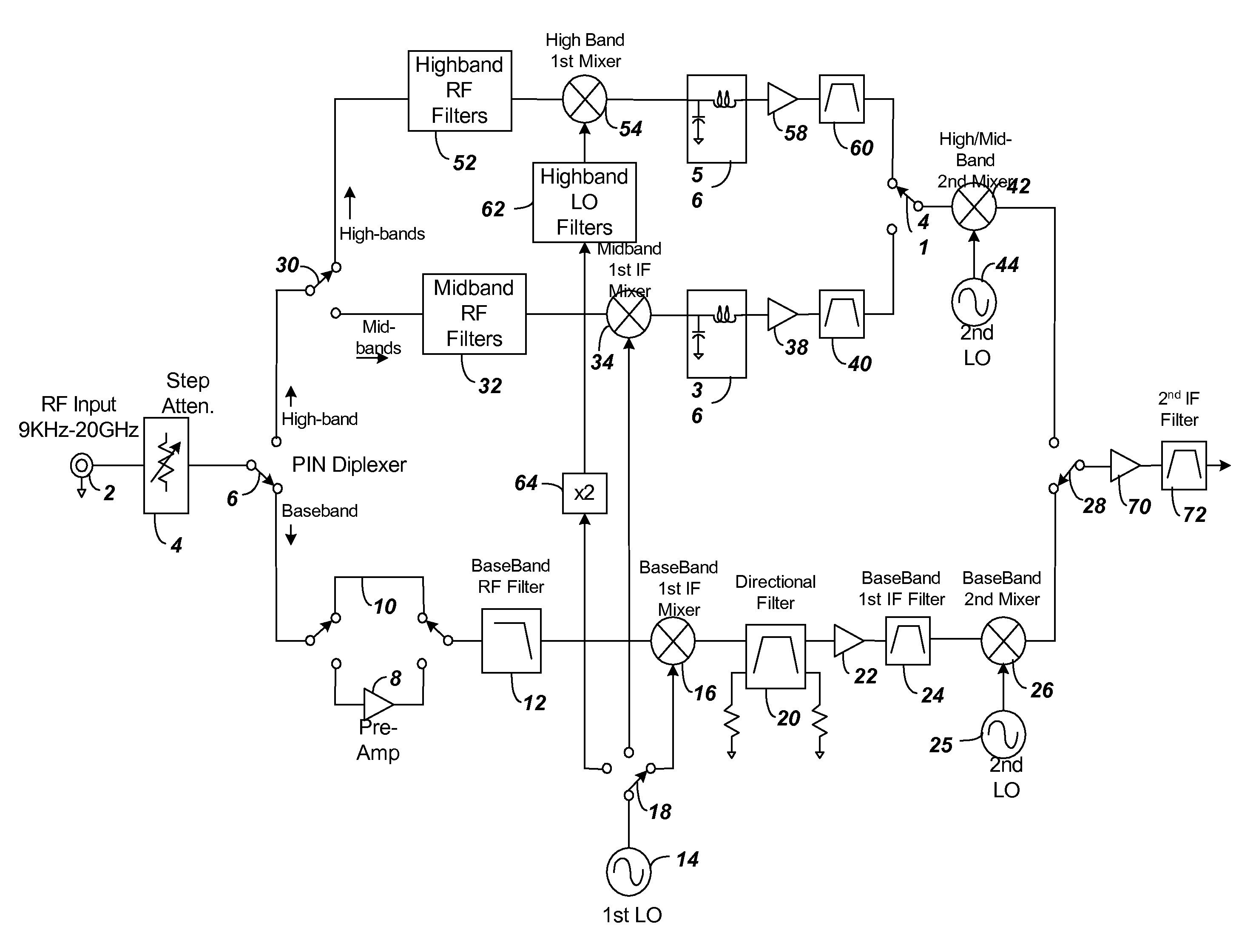
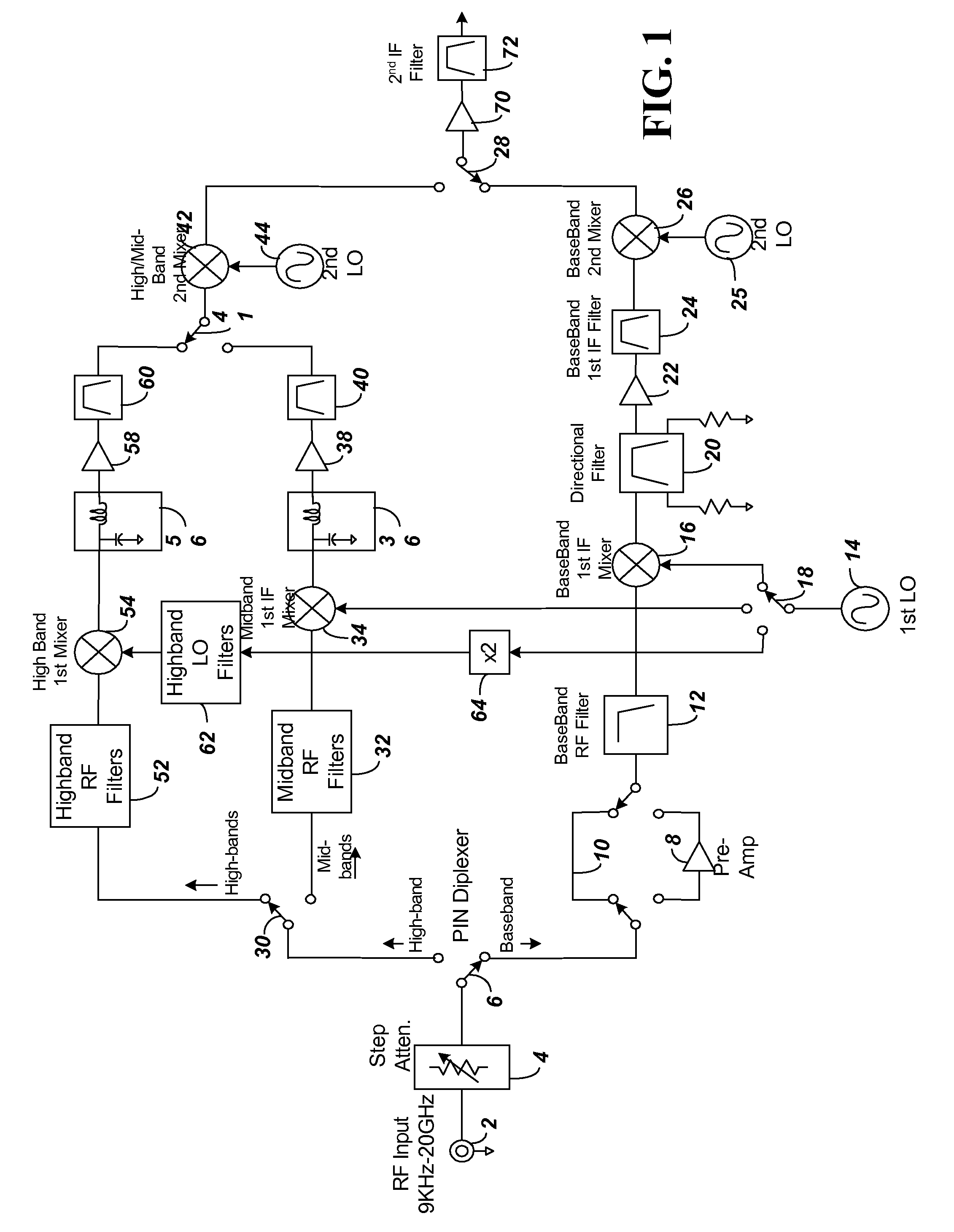
[0025]FIG. 1 shows a simplified block diagram of components of a spectrum analyzer according to embodiments of the present invention. The following description along with subsequent figures describes the function of the interconnected blocks of FIG. 1, as well as additional details about components shown in block diagram in FIG. 1.

I. Input Path to Spectrum Analyzer

[0026]An electrical signal to be analyzed enters the spectrum analyzer at port 2 through a coaxial connector. For purposes of illustration, the input is shown from 9 kHz-20 GHz, although an alternative input frequency range can be used. The signal passes from input 2 through to a step attenuator 4. The attenuator 4 for the example shown can provide 0 to 65 dB of attenuation, settable in 5 dB increments. The attenuator 4 is used to adjust signal level to within the spectrum analyzer's useful input amplitude range.

[0027]A. Precision Stand Alone Step Attenuator

[0028]The attenuator 4 is an electromechanical step attenuator tha...


PUM


Abstract

A spectrum analyzer is provided that includes components to achieve from below 9 kHz to above 20 GHz operation range while remaining hand-held. Components of the spectrum analyzer include an integrated precision stand-alone step attenuator that does not rely on printed circuit board (PCB) mounted circuit elements within the signal path. Further, a PIN diplexing switch separates signals into different base-band and highband paths. The baseband path includes a pre-amplifier for low frequency signals, while the higher frequency bands may not necessarily include a pre-amplifier. The baseband path further provides improved broadband termination of its 1st mixer IF port by incorporating a new quadrature-coupled directional (QCD) filter that includes a ring resonator. An inexpensive air dielectric multi-cavity baseband filter is also used to suppress 2nd mixer IF images. The highband path incorporates multi-throw MMIC PIN diode switches to selectively filter different bands of input signals. At least three total 1st mixers are used to increase operation bandwidth. A phase locked loop providing a 1st LO to the 1st mixers is created that uses a divide-by-two frequency divider in cascade with a sampler-type frequency downconverter. The output of the 1st LO is frequency doubled and filtered to increase the frequency range of the highband signal path.

Description

CLAIM OF PRIORITY TO PROVISIONAL APPLICATION[0001]This application claims priority under 35 U.S.C. 119(e) to U.S. Provisional Application No. 61 / 015,623, entitled “Hand-Held Microwave Spectrum Analyzer,” with filing date of Dec. 20, 2007, which is incorporated by reference herein in its entirety.BACKGROUND[0002]1. Technical Field[0003]The present invention relates to a handheld spectrum analyzer, and more particularly over components to enable the spectrum analyzer to operate over a wide bandwidth.[0004]2. Related Art[0005]Currently available hand-held microwave spectrum analyzers have an input frequency range of up to 7.1 GHz. Examples include the Anritsu MS2721B (7.1 GHz), and the Rohde+Schwarz FSH-6 (6 GHz). An external frequency converter can be connected to downconvert a received input signal to the spectrum analyzer and effectively boost the frequency range of the handheld spectrum analyzer. But adding the external frequency converter may create a device that is no longer hand...

Claims


Application Information

Patent Timeline
Patent Type & Authority Applications(United States)
IPC IPC(8): G01R23/14H03H7/00H01P1/20H03H7/24
CPCG01R23/16H03H7/463H01P1/2135
Inventor BROWN, RUSSELL A.ROBINSON, CINDY
Owner ANRITSU CO
Why Eureka
Try Eureka