
Dual clutch transmission having simplified controls

a technology of clutch transmission and simplified control, which is applied in the direction of fluid gearing, transportation and packaging, gearing, etc., can solve the problems of large and more expensive synchronizer, large synchronizer for first gear, and large synchronizer for synchronizer, etc., to achieve a smaller packaging envelope, reduce the effect of space occupation and simplify the construction

Inactive Publication Date: 2015-03-03
BORGWARNER INC
View PDF194 Cites 0 Cited by
  • Summary
  • Abstract
  • Description
  • Claims
  • Application Information

AI Technical Summary

Benefits of technology

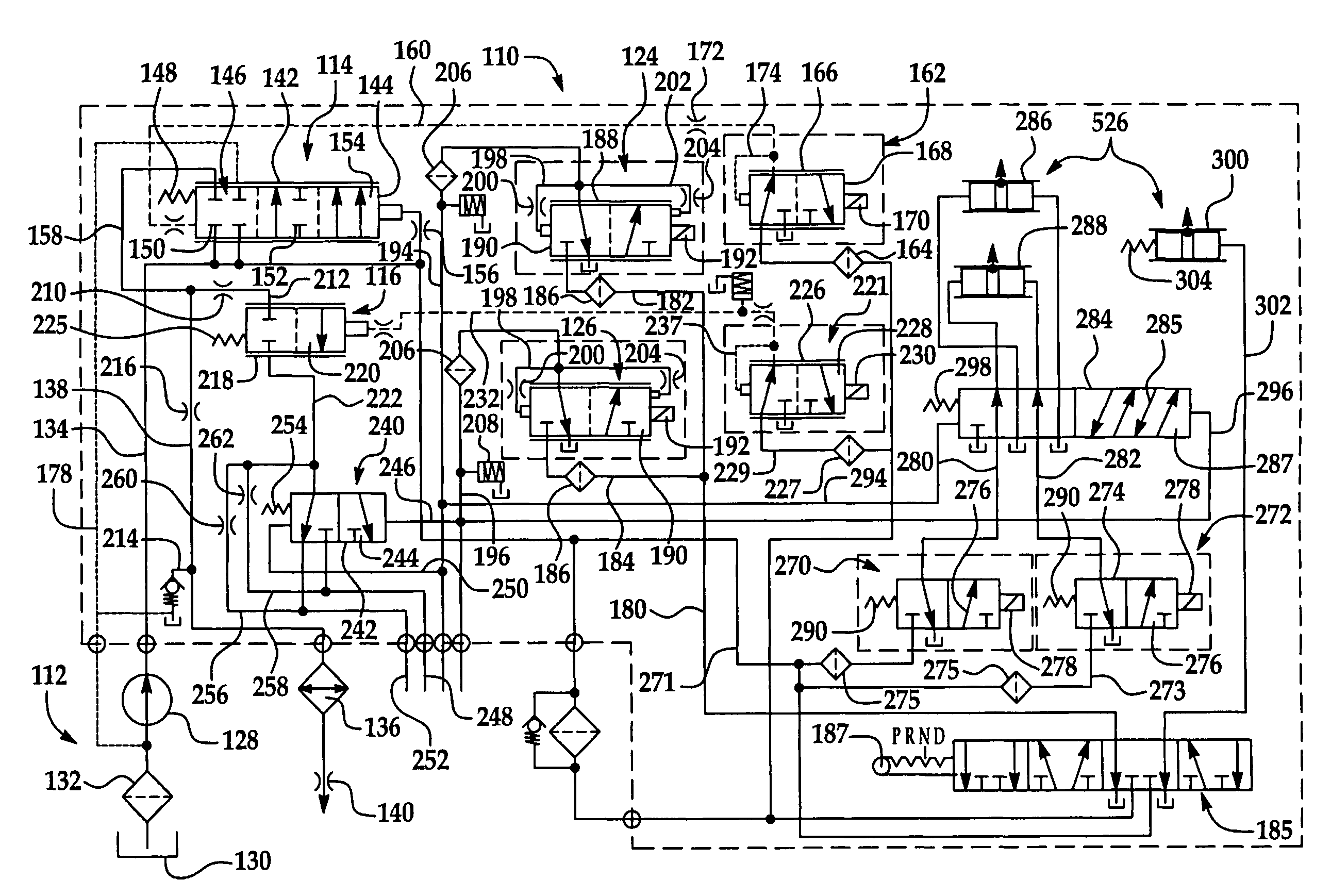
The present invention is a dual clutch transmission that has a simplified construction, reducing expensive components and allowing for a smaller packaging envelope. The transmission employs a simplified hydraulic circuit that provides cooling fluid and control to the clutch assemblies but has a much reduced complexity resulting in lower cost. The technical effects of the invention are improved operational characteristics and reduced complexity and cost.

Problems solved by technology

However, dual clutch transmissions of this type suffer from certain disadvantages.
In general, the more capacity that is required for the synchronizer, the larger and more costly the synchronizer is.
For example, the synchronizers for first gear typically are larger and more costly than the synchronizers for the other gears, and may be of a different more complex construction, such as a multi-cone synchronizer.
These more complicated, more costly synchronizers also raise additional durability and service issues.
For example, the diameter of the first gear, which is typically the largest gear diameter, is often a factor that limits efforts to reduce the diameter of the overall transmission.
In addition, the number of gears on the countershaft can be a limiting factor on the minimum length of the transmission, because the gears are typically aligned in series, with a separate countershaft gear provided for each of the gears of the input shaft for the different gear ratios.
In order to provide sufficient cooling to the clutch assemblies of the conventional dual clutch transmission, the clutch assemblies are usually bathed in transmission fluid in a generally uncontrolled manner.
While dual clutch transmissions have overcome several drawbacks associated with conventional transmissions and the newer automated manual transmissions, it has been found that controlling and regulating the automatically actuated dual clutch transmission to achieve the desired vehicle occupant comfort goals is a complicated matter.
In addition, the clutch and complex gear mechanisms, working within the close confines of the dual clutch transmission case, generate a considerable amount of heat.

Method used


Image

  • Dual clutch transmission having simplified controls
  • Dual clutch transmission having simplified controls
  • Dual clutch transmission having simplified controls

Examples


Embodiment Construction

)

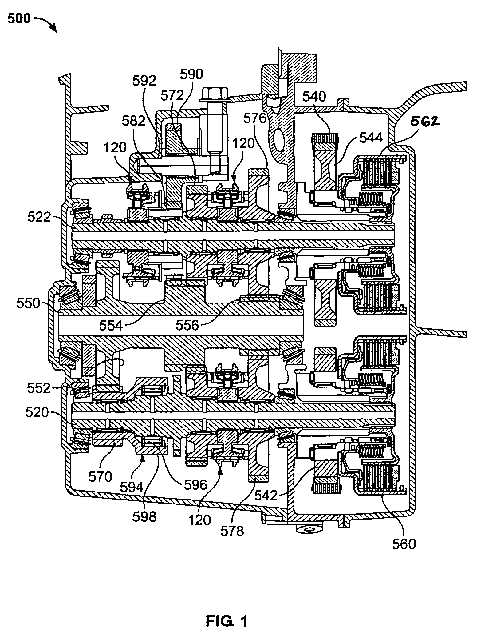
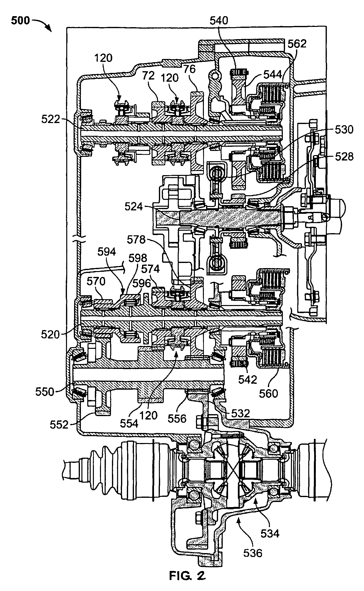
[0021]A representative example of the dual clutch transmission of the present invention is generally indicated at 500 in FIGS. 1 and 2 where like numerals are used to describe like components throughout the figures. Specifically, as shown in FIG. 1, the dual clutch transmission 500 includes pair of clutches, generally indicated at 560 and 562, respectively, a first or odd input shaft, generally indicated at 520, a second or even input shaft, generally indicated at 522, a counter shaft, generally indicated at 550, an output shaft 536, and a plurality of synchronizers, as will be described in greater detail below.

[0022]The dual clutch transmission 500 forms a portion of a vehicle powertrain and is responsible for taking a torque input from a prime mover, such as an internal combustion engine, and transmitting the torque through selectable gear ratios to the vehicle drive wheels. The dual clutch transmission 500 operatively routes the applied torque from the engine through the dual cl...


PUM


Abstract

A dual clutch transmission (500) having a plurality of forward gears and at least one reverse gear (582) where the first gear is operatively engaged by a one-way clutch (594). A pair of actuator control valves (270, 272) is employed to move actuators to engage selective ones of the forward gear sets. A multiplex valve (284) is disposed in fluid communication between the pair of actuator control valves (270, 272) and the actuators associated with the forward gears of the transmission and is adapted to selectively provide fluid communication to the actuators to thereby select the forward gear ratios. A manual valve (185) is operatively connected to the gear shift selector (187) to control the actuator associated with reverse gear (582).

Description

BACKGROUND OF THE INVENTION[0001]1. Field of the Invention[0002]The present invention relates, generally, to dual clutch transmissions and, more specifically, to dual clutch transmissions having an area controlled hydraulic circuit used for governing the flow of cooling fluid provided to each of the two clutches of a dual clutch transmission.[0003]2. Description of the Related Art[0004]Generally speaking, land vehicles require a powertrain consisting of three basic components. These components include a power plant (such as an internal combustion engine), a power transmission, and wheels. The power transmission component is typically referred to simply as the “transmission.” Engine torque and speed are converted in the transmission in accordance with the tractive-power demand of the vehicle. One type of transmission that has been proposed for use in conventional motor vehicles includes automated manual-type transmissions.[0005]Some automated manual type transmissions can be power-sh...

Claims


Application Information

Patent Timeline
Patent Type & Authority Patents(United States)
IPC IPC(8): F16H31/00F16H3/00F16H3/093F16H61/02F16H61/688
CPCF16H61/688F16H61/0206F16H3/006F16H3/093F16H61/0251F16H2200/0047Y10T74/19149Y10T74/19228Y10T74/20024
Inventor KOENIG, MELISSABUCHANAN, MARK
Owner BORGWARNER INC
Learn More