Digital broadcasting receiving unit and digital broadcasting system

Inactive Publication Date: 2007-11-01
RENESAS ELECTRONICS CORP
View PDF5 Cites 1 Cited by
  • Summary
  • Abstract
  • Description
  • Claims
  • Application Information

AI Technical Summary

Benefits of technology

[0012]An object of the present invention is to provide a digital broadcasting receiving unit capable of, without using a crystal oscillator having a variable freq

Problems solved by technology

The time stamp information may be lost under bad receiving condition.
On the other hand, because color shift of an image, noise, noise of sound or the like is generated easily when the frequency deflection of the receiving unit side clock is large, the frequency deflection of the receiving uni

Method used


Image

  • Digital broadcasting receiving unit and digital broadcasting system
  • Digital broadcasting receiving unit and digital broadcasting system
  • Digital broadcasting receiving unit and digital broadcasting system

Examples


first embodiment

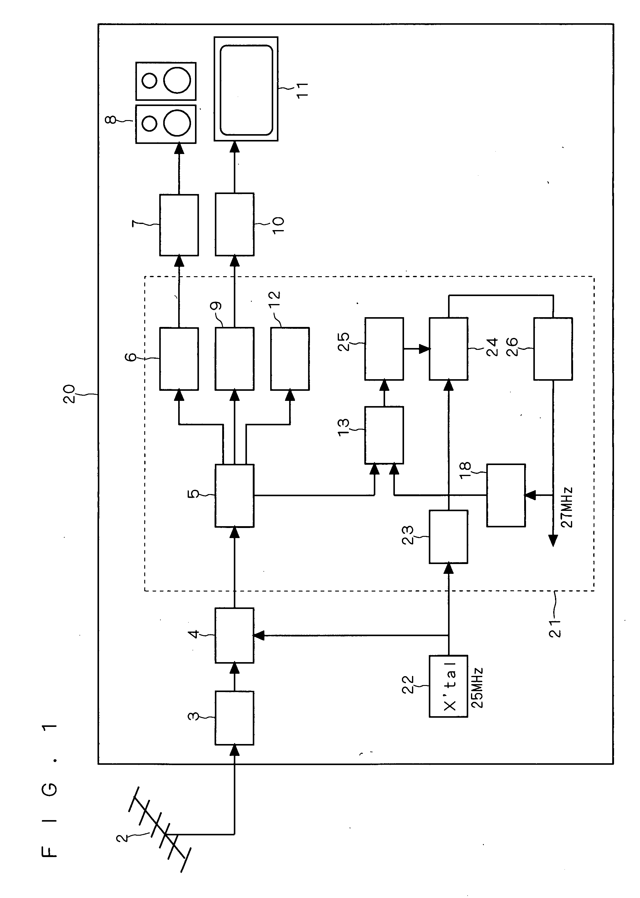
[0025]FIG. 1 is a block diagram showing the structure of a receiving unit 20 according to this embodiment.

[0026]As shown in FIG. 1, the receiving unit 20 comprises an antenna 2, a tuner 3, a demodulator 4, a digital analog (DA) converter 7, a speaker 8, a display circuit 10, a display device 11 (for example, liquid crystal panel), a decoder LSI (large scale integration) 21, and a crystal oscillator (which can be grasped as fixed frequency oscillator) 22.

[0027]The decoder LSI 21 comprises a system decoder (which can be grasped as reference time information detecting portion) 5, an audio decoder 6, a video decoder 9, a control CPU (central processing unit) 12, a phase comparator (which can be grasped as a difference detector) 13, a reference counter (can be grasped as a time information generating portion) 18, a multiplier 23, a variable digital dividing circuit (which can be grasped as a variable digital dividing portion) 24, a division ratio control circuit (which can be grasped as ...

second embodiment

[0081]FIG. 4 is a block diagram showing the structure of a digital broadcasting receiving unit (hereinafter referred to as receiving unit) 40 according to this embodiment. The receiving unit 40 of this embodiment is different from the receiving unit 20 of the first embodiment in following points.

[0082]If paying attention to the structures of the decoder LSI 21 in FIG. 1 and a decoder LSI 41 in FIG. 4, according to this embodiment, a PLL circuit 42 is inserted in between the variable digital dividing circuit 24 and the dividing circuit 26. The other structure is the same between both the receiving units 20 and 40.

[0083]The PLL circuit 42 outputs a clock (having a synchronous frequency) synchronous with a clock outputted from the variable digital dividing circuit (which can be grasped as variable digital dividing portion) 24. Then, the clock having the synchronous frequency is inputted to the reference counter (which can be grasped as a time information generating portion) 18 through ...

third embodiment

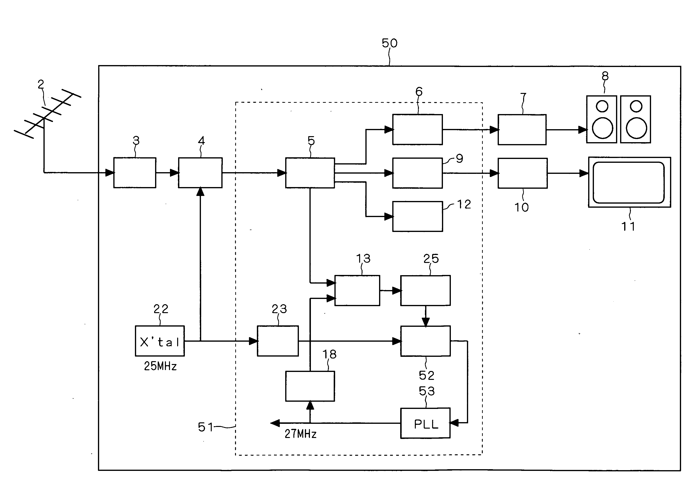
[0090]FIG. 5 is a block diagram showing the structure of a digital broadcasting receiving unit (hereinafter referred to as receiving unit) 50 of this embodiment. The receiving unit 20 of the first embodiment is different from the receiving unit 50 of this embodiment in following points.

[0091]Attention is paid to the structures of the decoder LSI 21 in FIG. 1 and a decoder LSI 51 in FIG. 4. First, the variable digital dividing circuit 24 and a variable digital dividing circuit 52 are different from each other in their internal structure. In the meantime, the internal structure of the variable digital dividing circuit 52 will be described with reference to FIG. 6.

[0092]In the first embodiment, the dividing circuit 26 is disposed between the variable digital dividing circuit 24 and the reference counter (which can be grasped as time information generating portion) 18. Contrary to this, according to this embodiment, a PLL circuit 53 is disposed between the variable digital dividing circ...


PUM


Abstract

This invention provides a digital broadcasting receiving unit capable of achieving synchronization of time information between a base station and a receiving unit with reference clock without use of a crystal oscillator (VCXO) having a variable frequency. The crystal oscillator oscillates a clock of a predetermined fixed frequency. A variable digital dividing circuit divides a fixed frequency by a division ratio so as to change the division ratio. A system decoder detects reference time information from the base station. A reference counter generates time information of a receiving unit. A phase comparator detects a difference between reference time information and time information. A division ratio control circuit controls the change of the division ratio based on the difference. The reference counter generates time information based on a clock having a frequency obtained by dividing by the variable digital dividing circuit and feeds back time information to the phase comparator.

Description

BACKGROUND OF THE INVENTION[0001]1. Field of the Invention[0002]The present invention relates to a digital broadcasting receiving unit and a digital broadcasting system.[0003]2. Description of the Background Art[0004]Conventionally, a digital broadcasting receiving unit (hereinafter referred to as receiving unit) for home use has been so constructed that a base station and the receiving unit are operated according to a common clock and time information by accurately synchronizing the reference clock of the base station (broadcasting station) with the reference clock of the receiving unit at home. This method has been described in MPEG2 standard (ISO_IEC—13818-1, Appendix D).[0005]This receiving unit utilizes an expensive crystal oscillator having a variable frequency (hereinafter referred to as VCXO) in order to accurately synchronize the reference clock of the base station with the reference clock of the receiving unit. The operation of the receiving unit having the VCXO will be br...

Claims


Application Information

Patent Timeline
IPC IPC(8): H04B1/66H03L7/00H04B1/16H04N5/44H04N7/173
CPCH04N21/4305
Inventor SHIROTA, HIROSHISAITO, TADASHIITO, KAZUYUKIOKUDA, RYOSUKEARAMOTO, MASAO
Owner RENESAS ELECTRONICS CORP
Why Eureka
Try Eureka