Imaging lens

a technology of imaging lenses and occlusion, applied in the field of imaging lenses, can solve the problems of weak power of the first lens, disadvantageous in order to achieve thinness, and insufficient brightness of the imaging lens, so as to shorten the total track length, and achieve mass production

Active Publication Date: 2015-01-13
TOKYO VISIONARY OPTICS CO LTD
View PDF8 Cites 4 Cited by
  • Summary
  • Abstract
  • Description
  • Claims
  • Application Information

AI Technical Summary

Benefits of technology

[0010]The present invention has been made in view of the above problem and has an objective to provide an imaging lens composed of five lenses which can achieve compactness and thinness, has a small F-value and corrects various aberrations properly and provides a relatively wide angle of view and also meets the need for cost reduction.

Problems solved by technology

However, since its F-value is about 3.0, therefore, the imaging lens is not considered to provide enough brightness to cope with the increasing trend toward image sensors with a larger number of pixels.
Although the imaging lens described in Patent Document 2 is a lens system which has an F-value of 2.05 to 2.5 to ensure sufficient brightness and provides high aberration correction capability, the power of its first lens is weak, so it is disadvantageous in order to achieve thinness.

Method used


Image

  • Imaging lens
  • Imaging lens
  • Imaging lens

Examples


embodiment 1

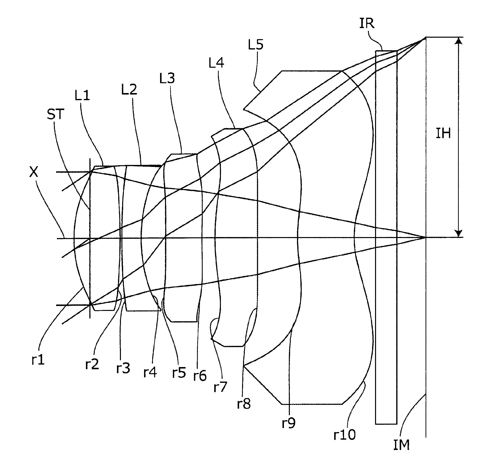
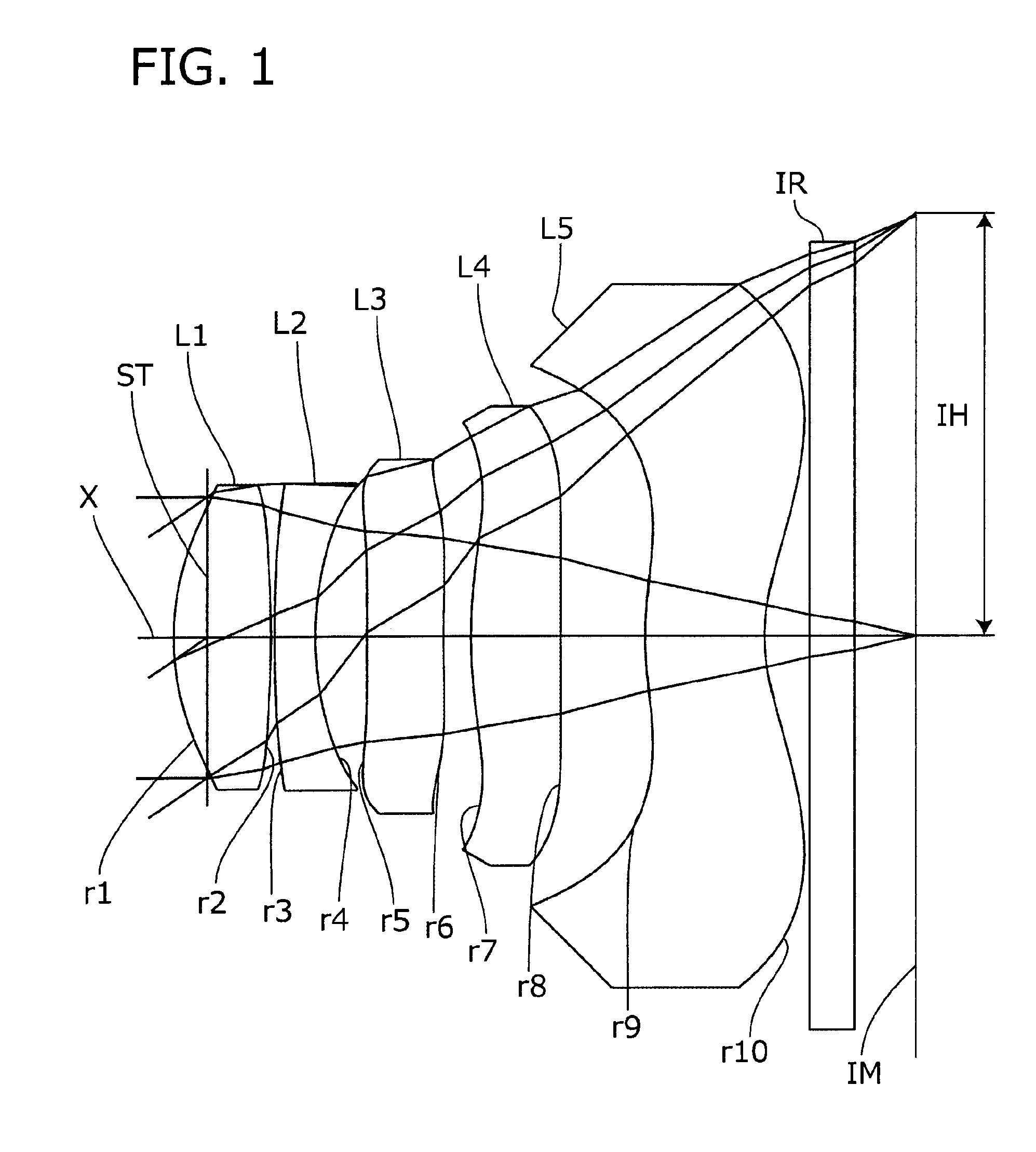
[0053]Next, the preferred embodiments of the present invention will be described in detail referring to the accompanying drawings. FIGS. 1, 3, 5, and 7 are views showing the general configurations of imaging lenses according to Embodiments 1 to 4 of the present invention respectively. Since all these Embodiments have the same basic lens configuration, the lens configuration of an imaging lens according to the present invention is explained below referring to the view of the

[0054]As shown in FIG. 1, in the imaging lens according to the present embodiment, lenses are arranged in the following order from the object side to the image side: a first lens L1 with positive refractive power, a second lens L2 with negative refractive power, a third lens L3 with positive or negative refractive power, a fourth lens L4 with positive refractive power, and a fifth lens L5 with negative refractive power. Aperture stop ST is located on the object side of the first lens L1. Filter IR is located betwe...

embodiment 2

[0080

[0081]The basic lens data of the Embodiment 2 is shown below in Table 2.

[0082]

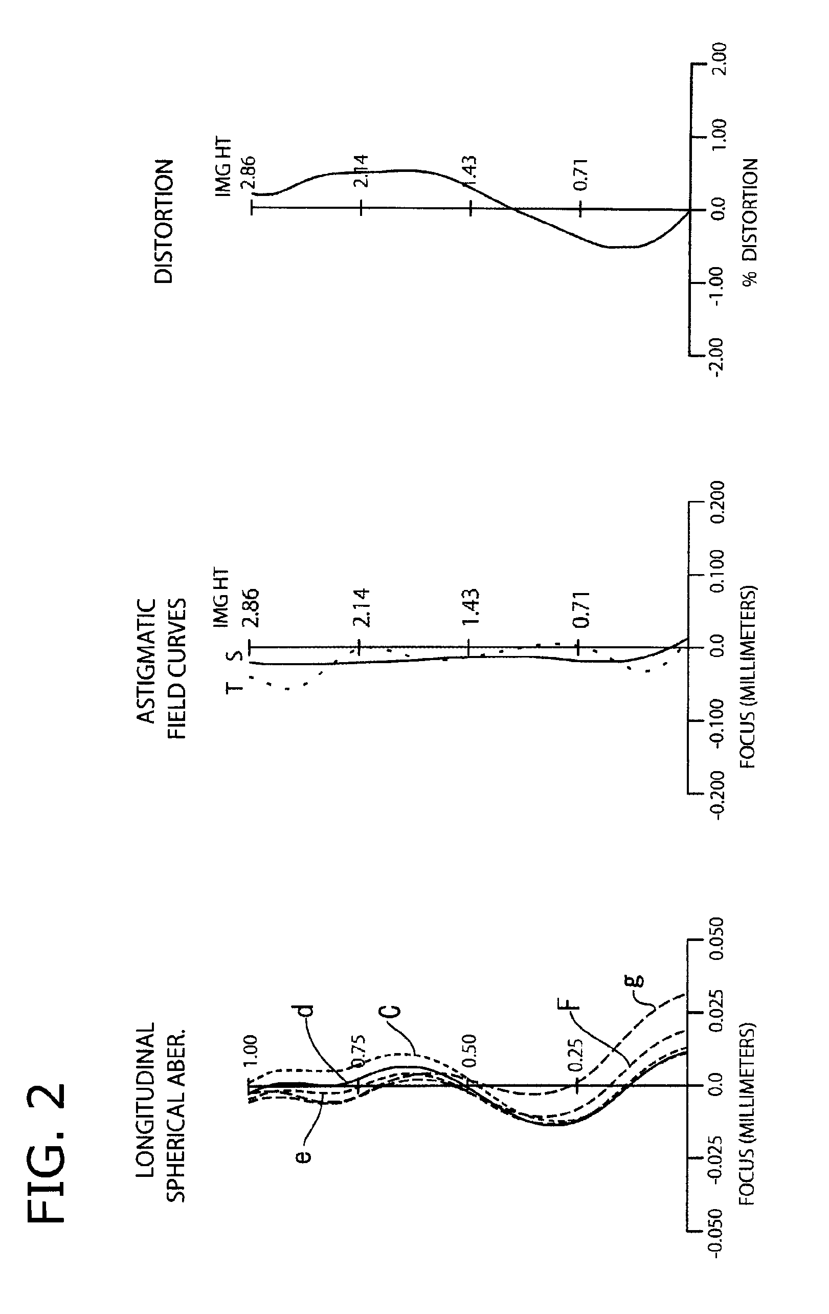
TABLE 2Unit mmf = 4.159Fno = 2.20ω(°) = 34.50IH = 2.856Surface dataSurfaceCurvatureSurfaceRefractiveAbbe No.No. iradius rdistance dindex Ndνd(Object surface)InfinityInfinityStopInfinity−0.2251*1.8740.5841.53556.162*−21.9650.1003*33.4380.2601.63523.914*2.3430.2385*3.8660.6101.53556.166*11.0670.3867*4.1330.5051.53556.168*41.2700.4609*2.3150.7231.53556.1610* 1.2610.411 Infinity0.31.51764.2012 Infinity0.486Image planeInfinitySingle lens dataLensStart planeFocal length113.24423−3.9393510.749478.51559−6.788Aspheric dataFirstSecondThirdFourthFifthsurfacesurfacesurfacesurfacesurfacek−1.886E+004.388E+023.059E−02−1.458E+00  0.000E+00A4 3.969E−021.085E−013.059E−02−1.085E−01 −1.362E−01A6−2.319E−02−1.011E−01 3.157E−022.070E−01 3.780E−02A8 5.384E−022.255E−02−1.821E−01 −3.220E−01  4.319E−03A10−4.879E−02−1.427E−02 1.166E−012.360E−01−2.479E−02A12 3.911E−03−2.987E−03 −1.491E−02 −5.626E−02  6.121E−02A14 5.711E−034.239E−...

embodiment 3

[0086

[0087]The basic lens data of the Embodiment 3 is shown below in Table 3.

[0088]

TABLE 3Unit mmf = 4.142Fno = 2.20ω(°) = 34.75IH = 2.856Surface dataSurfaceCurvatureSurfaceRefractiveAbbe No.No. iradius rdistance dindex Ndνd(Object surface)InfinityInfinityStopInfinity−0.2001*1.8720.5911.53556.162*−5.5480.0473*6.3550.2761.63523.914*1.7100.4585*8.5000.3921.53556.166*9.6000.3387*7.5280.5231.53556.168*736.7530.2489*1.9730.8481.53556.1610* 1.5090.411 Infinity0.31.51764.2012 Infinity0.600Image planeInfinitySingle lens dataLensStart planeFocal length112.68223−3.73335122.8794714.16459−33.034Aspheric dataFirstSecondThirdFourthFifthsurfacesurfacesurfacesurfacesurfacek−2.217E+00 0.000E+000.000E+00−9.585E−01 0.000E+00A43.626E−021.141E−012.186E−02−9.693E−02 −1.324E−01 A6−2.837E−02 −1.313E−01 5.007E−022.423E−015.992E−02A83.465E−024.347E−02−1.746E−01 −3.158E−01 3.496E−03A10−3.540E−02 −1.263E−02 1.461E−012.226E−01−3.148E−02 A120.000E+000.000E+00−3.230E−02 −5.368E−02 5.376E−02A140.000E+000.000E+000....


PUM


Abstract

An imaging lens includes five lenses for a solid-state image sensor, arranged in order from the object side to the image side, a first lens with positive refractive power having a convex object side surface, a second lens with negative refractive power having a concave image side surface, a third lens with positive or negative refractive power, a fourth lens with positive refractive power as a double-sided aspheric lens having a concave image side surface near an optical axis, and a fifth lens with negative refractive power as a double-sided aspheric lens having a concave image side surface near the optical axis, wherein the first lens and second lens satisfy conditional expressions below:45<ν1<90  (1)22<ν2<35  (2)2.0<ν1 / ν2<2.6  (3)whereν1: first lens Abbe numberν2: second lens Abbe number.

Description

[0001]The present application is based on and claims priority of Japanese patent application No. 2012-085263 filed on Apr. 4, 2012, the entire contents of which are hereby incorporated by reference.BACKGROUND OF THE INVENTION[0002]1. Field of the Invention[0003]The present invention relates to imaging lenses which form an image of an object on a solid-state image sensor such as a CCD sensor or C-MOS sensor used in a compact image pickup device and more particularly to imaging lenses composed of five lenses which are built in image pickup devices mounted in mobile terminals such as mobile phones and smart phones, which are becoming increasingly compact and thin, and PDAs (Personal Digital Assistances), game machines and information terminals such as PCs.[0004]2. Description of the Related Art[0005]In recent years, the market of mobile terminals with an image pickup device has been expanding increasingly. Today, most of such mobile terminals have a camera function. Nowadays, as for th...

Claims


Application Information

Patent Timeline
Patent Type & Authority Patents(United States)
IPC IPC(8): G02B9/60G02B13/18G02B13/00
CPCG02B13/0045G02B9/60G02B1/041
Inventor ISHIZAKA, TOHRU
Owner TOKYO VISIONARY OPTICS CO LTD
Why Eureka
Try Eureka