Energy transfer device

a technology of energy transfer device and fuses, which is applied in the direction of ammunition fuzes, lighting and heating equipment, borehole/well accessories, etc., can solve the problems of failure to detonate the primary explosive used in the blasting operation, the fuses generally are not designed or configured, and the longer time delay is desired beyond

Inactive Publication Date: 2015-02-03
CARTRIDGE ACTUATED DEVICES
View PDF21 Cites 14 Cited by
  • Summary
  • Abstract
  • Description
  • Claims
  • Application Information

AI Technical Summary

Benefits of technology

[0008]The present invention provides a solution to this problem by providing an energy transfer device configured to transfer the energy output from a first pyrotechnic device to a second pyrotechnic device for initiating firing of the second pyrotechnic device. In one embodiment, the energy transfer device comprises a metallic body having a forward section configured to be placed adjacent the first pyrotechnic device and an aft section configured to be placed adjacent the second pyrotechnic device. The metallic body further includes an axial passageway extending therethrough. The passageway includes a first segment extending through the body forward section and a second segment extending through the body aft section. The body forward section is deformable by the energy output from the first pyrotechnic device such that the diameter of the passageway first segment is narrowed thereby forming a constriction in the passageway.

Problems solved by technology

However, in certain applications, longer time delays are desired beyond what a single time delay fuse is configured to supply.
Time delay fuses generally are not designed or configured for use in this manner.
Thus, in certain circumstances, the output charge from the time delay fuse can fail to ignite the adjacent fuse, thereby resulting in failure to detonate the primary explosive used in the blasting operation.
In the context of downhole operations, failure to detonate the primary explosive may require that the tool including the primary explosive be run back up the hole and a new string of time delay fuses be installed.
Pulling pipe string is an expensive and time-consuming operation.
The presence of explosive devices further complicates this operation due to their inherently dangerous nature.

Method used


Image

  • Energy transfer device
  • Energy transfer device
  • Energy transfer device

Examples


Embodiment Construction

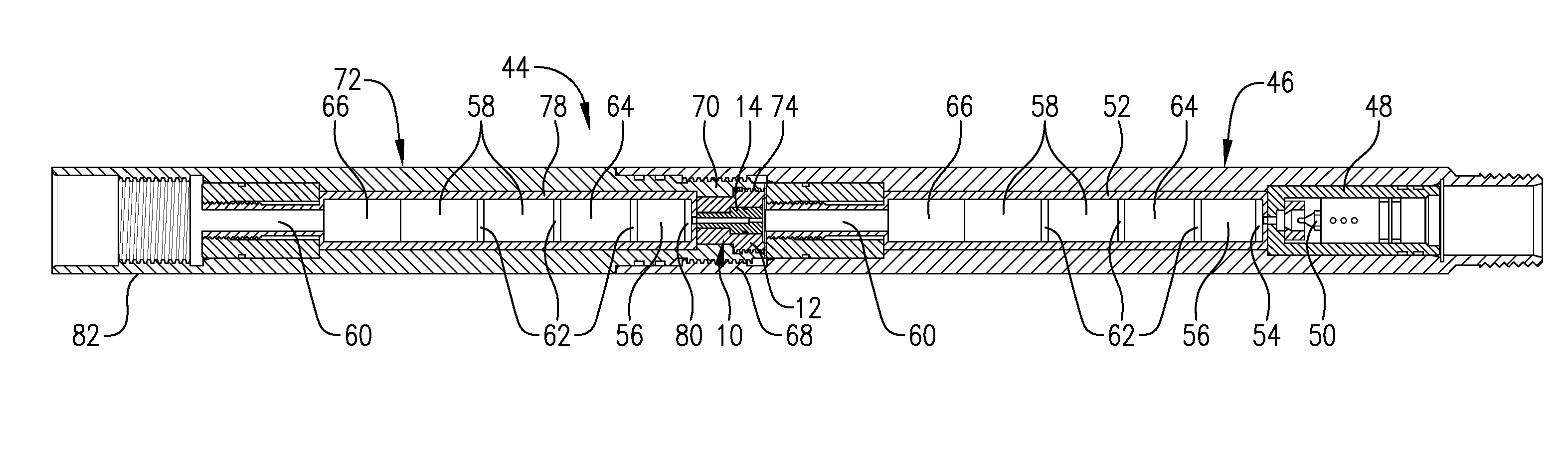
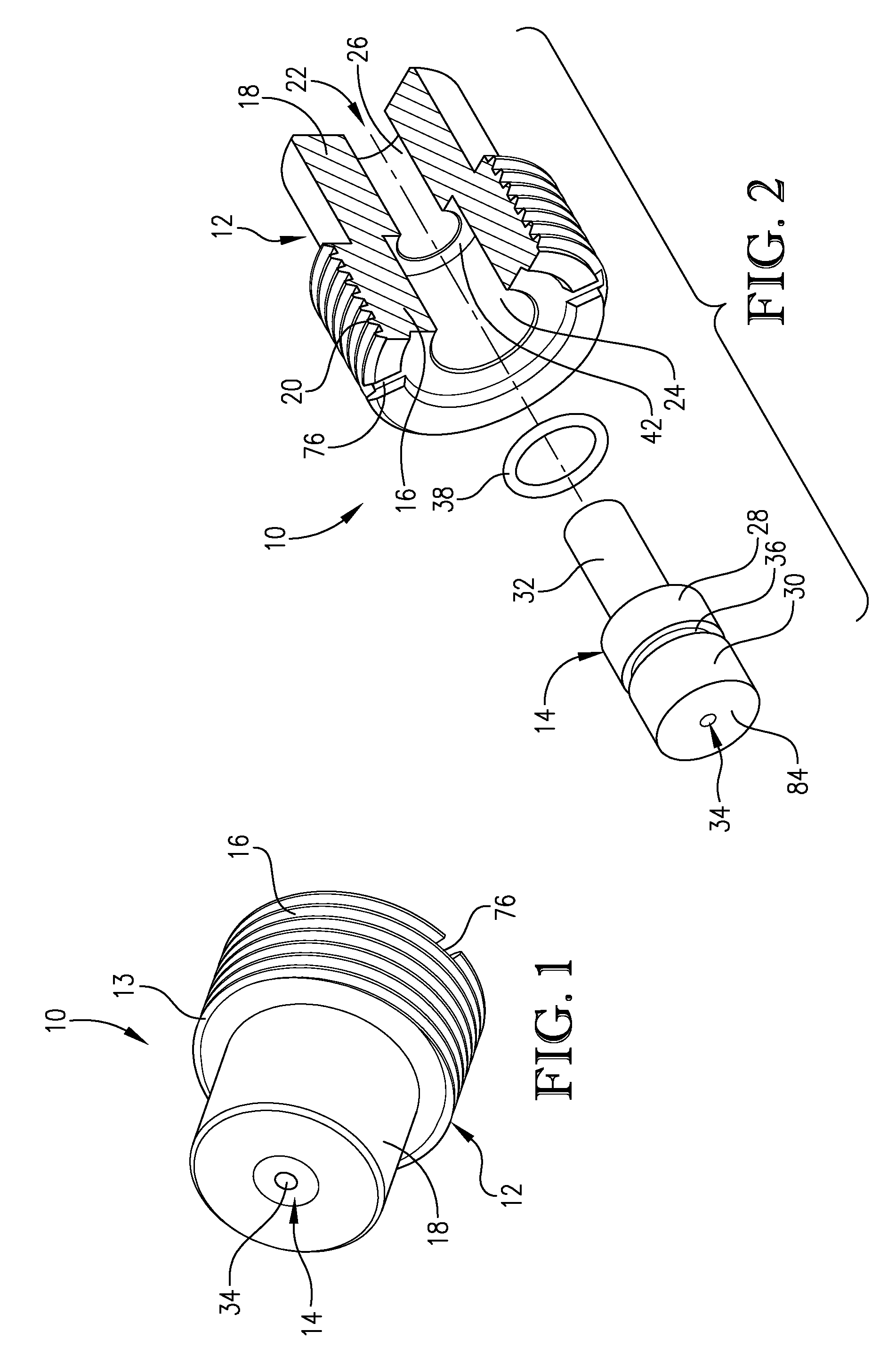
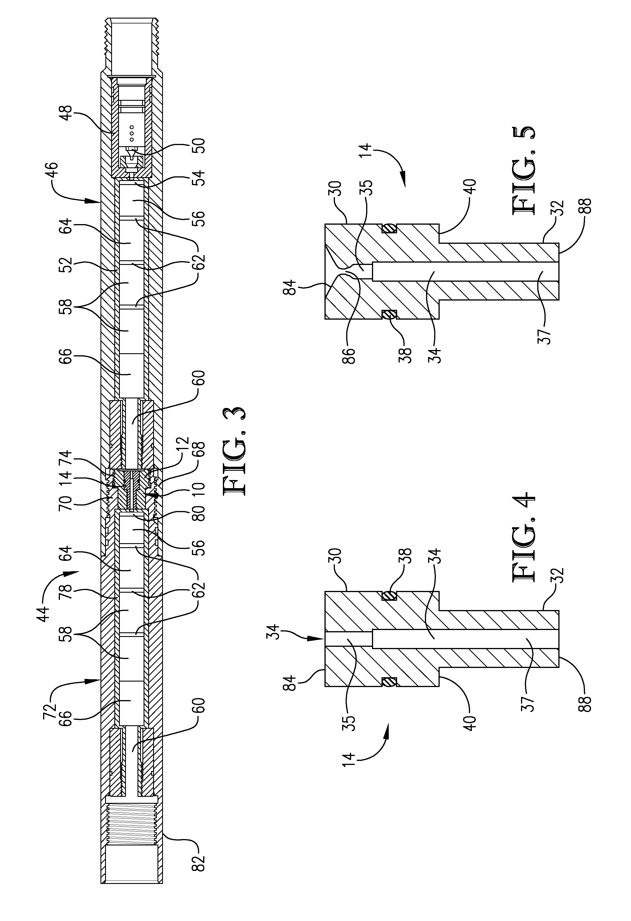
[0017]Turning now to the Figures, and in particular FIGS. 1 and 2, an energy transfer device 10 according to one embodiment of the present invention is shown. Device 10 is a dynamic device that is configured to limit and convert a detonating output of a time delay fuse or similar device so that the output is suitable to ignite another time delay fuse or similar device without damaging the input and resulting in a failure to ignite. Device 10 is of two-piece construction comprising a device housing 12 and a device insert 14. Housing 12 comprises a metallic body 13 that includes a generally cylindrical forward section 16 configured to be placed adjacent to and facing the pyrotechnic device that is supplying the energy to be transferred to another pyrotechnic device and a generally cylindrical aft section 18 configured to be placed adjacent to and facing the pyrotechnic device receiving the transferred energy. In certain embodiments, forward section 16 may have a larger outer diameter ...


PUM


Abstract

A energy transfer device (10) is provided that is capable of transferring the energy output from one pyrotechnic device (52) to another device (78) for initiating firing thereof. Device (10) comprises a device housing (12) in which a deformable device insert (14) is received. Device insert (14) comprises a central passageway (34) for transmitting the output from a pyrotechnic device (52), including energy, gasses, and / or solids, to another pyrotechnic device (78). The passageway (34) conducts the pyrotechnic device output to a precise location on the second pyrotechnic device (78) where firing is most effectively initiated. The energy transfer device (10) may be employed as a part of a tool (44) used in well completion operations.

Description

RELATED APPLICATION[0001]The present application claims the benefit of U.S. Provisional Patent Application No. 61 / 637,541, filed Apr. 24, 2012, which is incorporated by reference herein in its entirety.BACKGROUND OF THE INVENTION[0002]1. Field of the Invention[0003]The present invention is directed toward an energy transfer device that is configured to transmit energy released from the output of a first pyrotechnic device to a second pyrotechnic device in order to initiate firing of the second pyrotechnic device. The energy transfer device absorbs energy released by the output charge of the first pyrotechnic device, such as a time delay fuse, and directs at least a portion of the energy toward the second pyrotechnic device in a controlled manner so as to efficiently and reliably facilitate firing of the second pyrotechnic device.[0004]2. Description of the Prior Art[0005]Pyrotechnic devices are commonly employed to ignite or detonate explosive charges in a variety of industrial appl...

Claims


Application Information

Patent Timeline
Patent Type & Authority Patents(United States)
IPC IPC(8): F42C15/29E21B7/00F42C19/08F42D1/04
CPCF42D1/043E21B7/007F42C19/0815F42C19/0807F42C9/10E21B43/11F42C15/31C06C5/06
Inventor GREELEY, WILLIAMKULL, RAIVOSOOHOO, ED
Owner CARTRIDGE ACTUATED DEVICES
Why Eureka
Try Eureka