Reducing loss at intersection in optical waveguides
a technology of optical waveguides and intersections, applied in the direction of optical waveguide light guides, optical light guides, instruments, etc., can solve the problems of not describing the filling of the divided portions with clad materials, inevitable optical loss at intersections, etc., and achieve the effect of reducing the amount of light propagation loss (light leakage)
- Summary
- Abstract
- Description
- Claims
- Application Information
AI Technical Summary
Benefits of technology
Problems solved by technology
Method used
Image
Examples
first embodiment
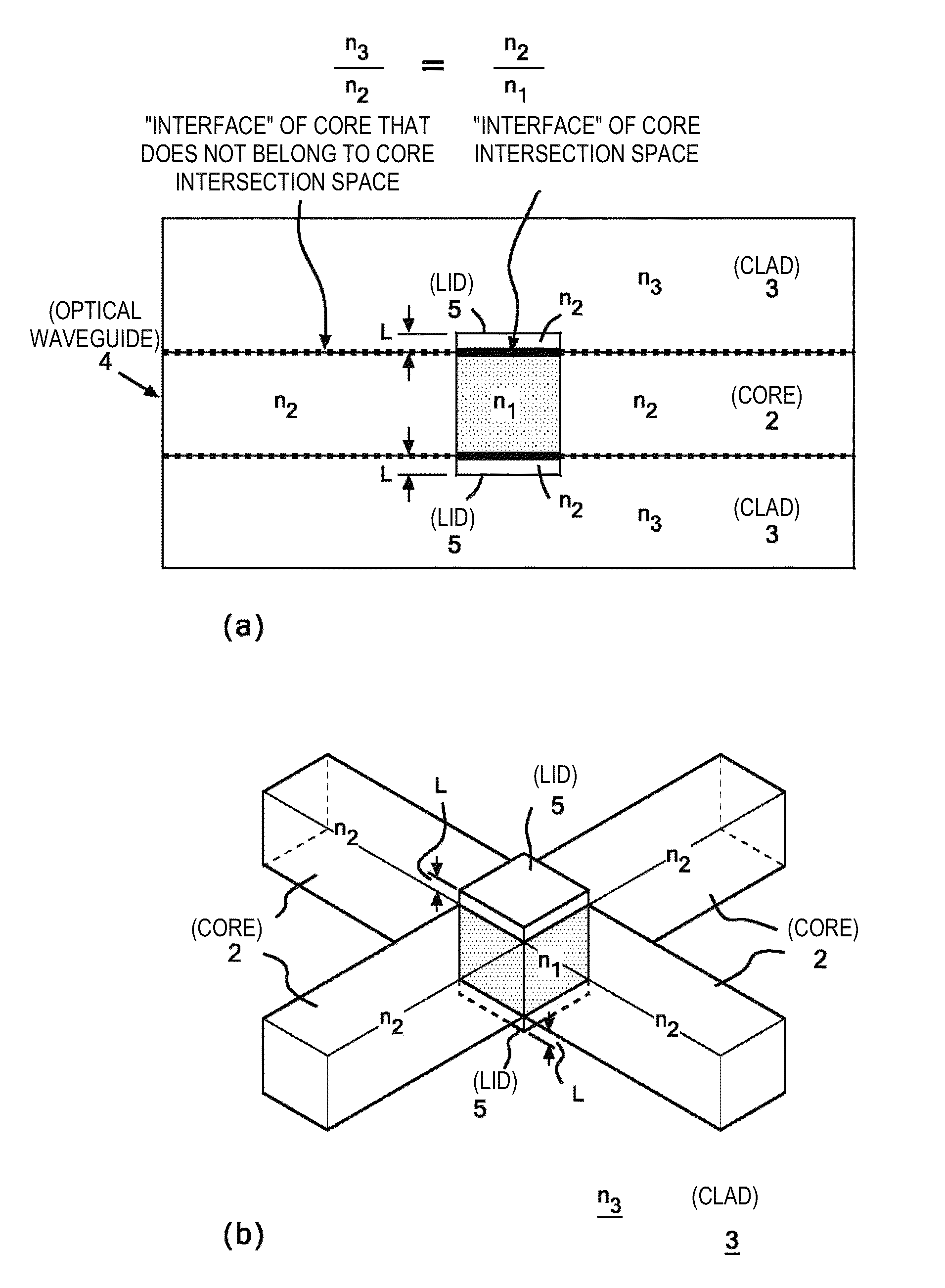
[0037]FIG. 4 shows the configuration of an intersection in an optical waveguide according to the present invention. The configuration shown in FIG. 4 is characterized in that portions on two planes, the upper and lower planes, of the core intersection space 1 described with reference to FIG. 3 are made of the same material as that of the cores 2 so that the same material as that of the cores 2 forms interfaces with the clad 3. In other words, the structure shown in FIG. 4 is characterized in that the portions on the upper and lower planes of the core intersection space 1 are not made of the clad material but form lids made of the same material as that of the cores 2.
[0038]The cross-sectional shape of each of the cores 2 is preferably substantially square to allow light to propagate isotropically. When the cross-sectional shape of each of the cores 2 is square, the core intersection space 1 has a cubic shape.
[0039]Technical significance of employing the characteristic configuration d...
second embodiment
[0046]FIG. 5 shows the configuration of an intersection in an optical waveguide according to the present invention. The configuration is characterized in that four discontinuity spaces between each pair of the cores 2 and the corresponding core intersection space 1, which are the four side planes that divide (isolate) the core intersection space 1 described with reference to FIG. 3, that is, locations where the core 2 should normally be connected to the core intersection space 1, are filled with the same material as that of the clad 3. In other words, the structure shown in FIG. 5 is characterized in that the four side planes of the core intersection space 1 are not filled with the core material so that the core intersection space 1 is seamlessly connected to the adjacent cores 2 but are filled with the same material as that of the clad 3.
[0047]The structure is, in other words, designed in consideration of using the same material not only to fill the discontinuity spaces, which are ...
PUM
 Abstract
Description
Claims
Application Information
 - R&D
- Intellectual Property
- Life Sciences
- Materials
- Tech Scout
- Unparalleled Data Quality
- Higher Quality Content
- 60% Fewer Hallucinations
Browse by: Latest US Patents, China's latest patents, Technical Efficacy Thesaurus, Application Domain, Technology Topic, Popular Technical Reports.
© 2025 PatSnap. All rights reserved.Legal|Privacy policy|Modern Slavery Act Transparency Statement|Sitemap|About US| Contact US: help@patsnap.com


