
Roller blind system for a motor vehicle

a technology for motor vehicles and blinds, applied in monocoque constructions, vehicle bodies, building components, etc., can solve the problems of affecting and affecting the appearance of the shade arrangement or the edge stiffening. , to achieve the effect of improving the optical performance of the shade arrangement or the edge stiffening, improving the optical performance, and improving the appearan

Inactive Publication Date: 2015-02-17
WEBASTO AG
View PDF38 Cites 15 Cited by
  • Summary
  • Abstract
  • Description
  • Claims
  • Application Information

AI Technical Summary

Benefits of technology

[0009]The object of this invention is to devise a shade arrangement for a motor vehicle in which the aforementioned disadvantages are avoided.

Problems solved by technology

However, when the shade length on such a shade arrangement is tensioned only between the pull and the take-up roller, even with relatively high tension in this direction, for example, for a partially opened roof opening over the shade length the latter can flutter.
Furthermore, the gap which is generally present in these embodiments on the edge of the shade length can be optically disruptive.
The above described shade arrangement, on the one hand, has the disadvantage that continuous bending of the edge stiffening along the bending line generates a critical region along which the shade arrangement or edge stiffening can be damaged and even tear by material fatigue.
On the other hand, to guide this edge stiffening a connecting link is required which borders the edge stiffening as it is guided and thus cannot be extruded; this increases construction and installation costs for this guide.
However, the disadvantage in this arrangement is the reset force of a torsion spring which varies greatly depending on the drawing length of the shade length.

Method used


Image

  • Roller blind system for a motor vehicle
  • Roller blind system for a motor vehicle
  • Roller blind system for a motor vehicle

Examples


Embodiment Construction

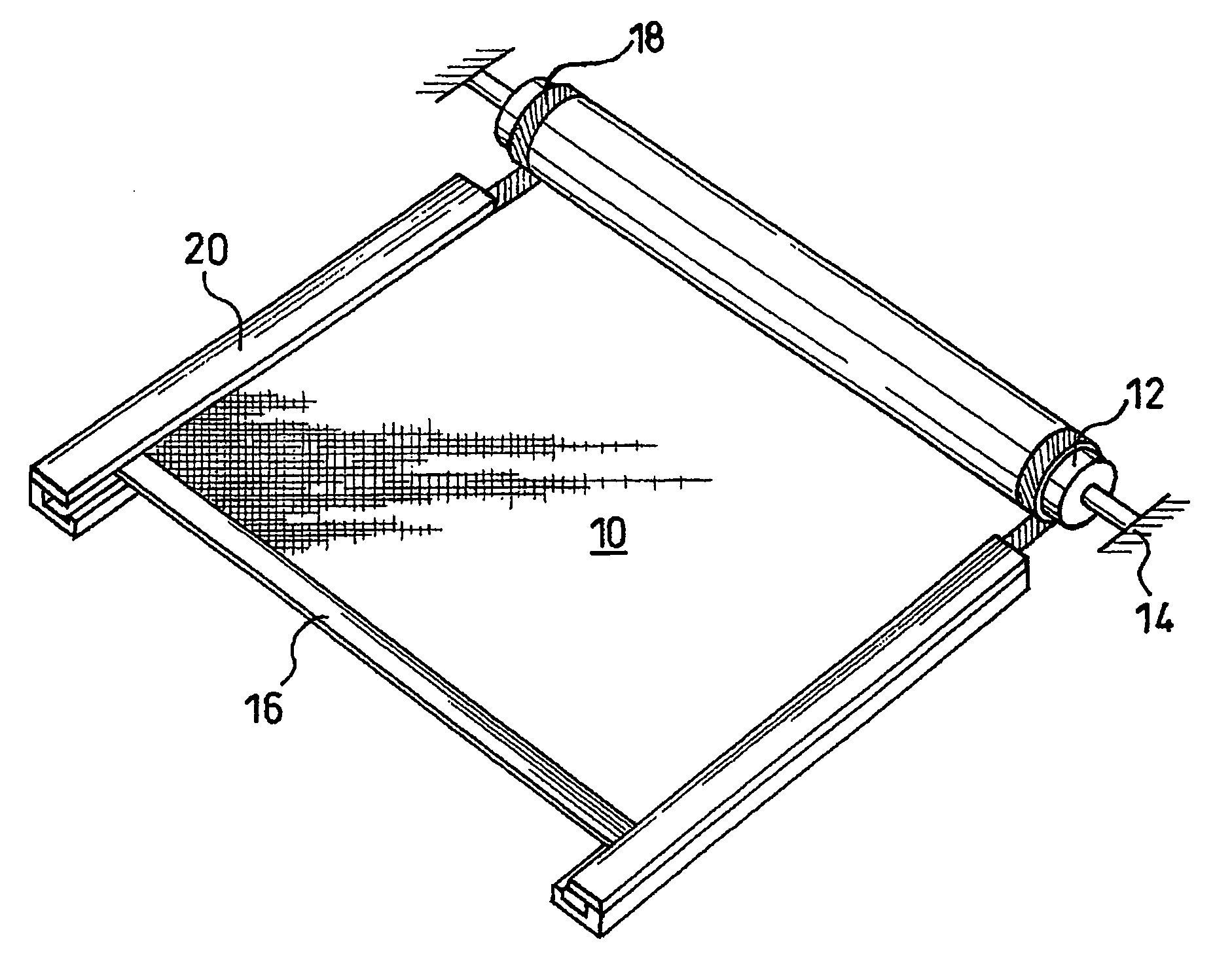
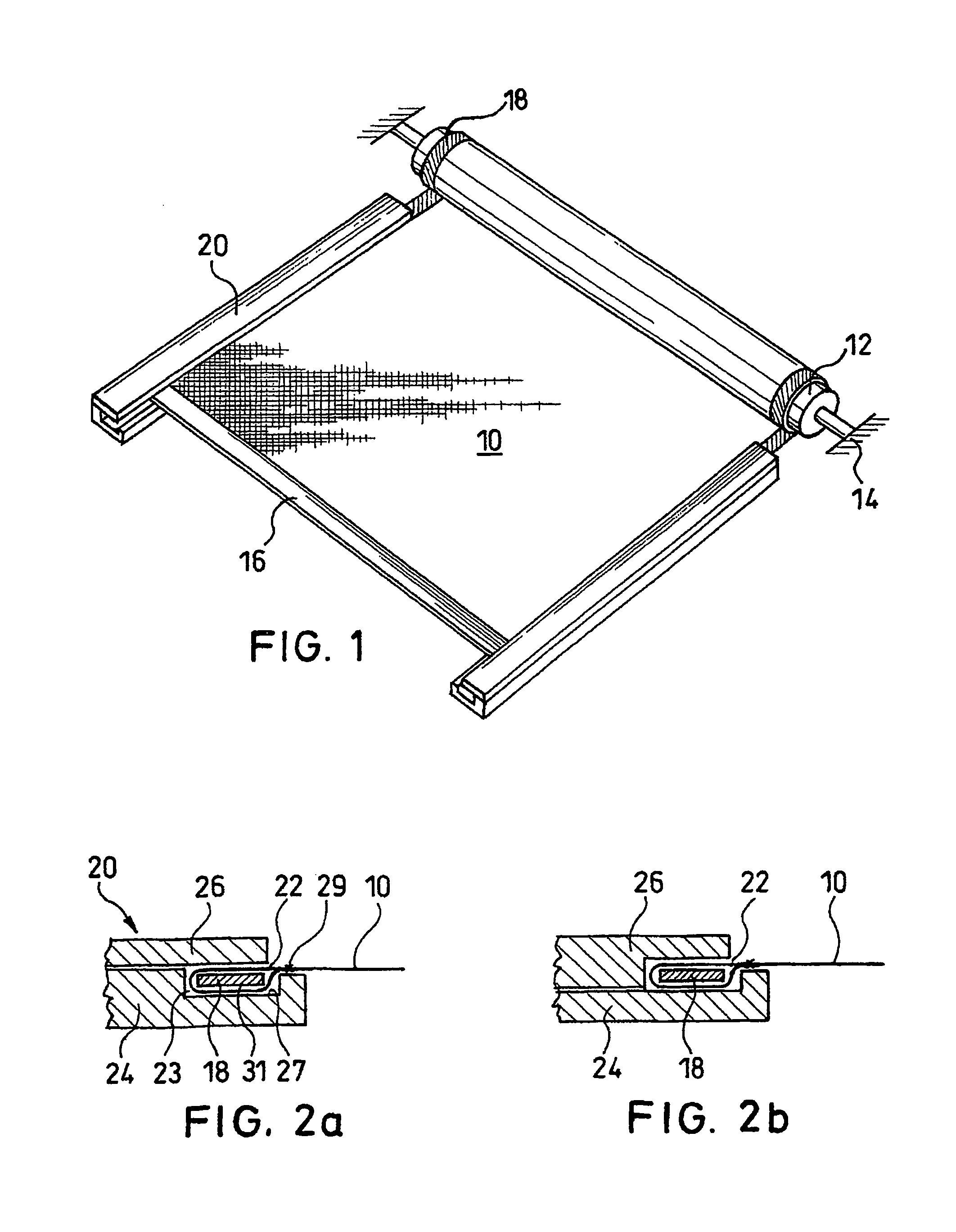
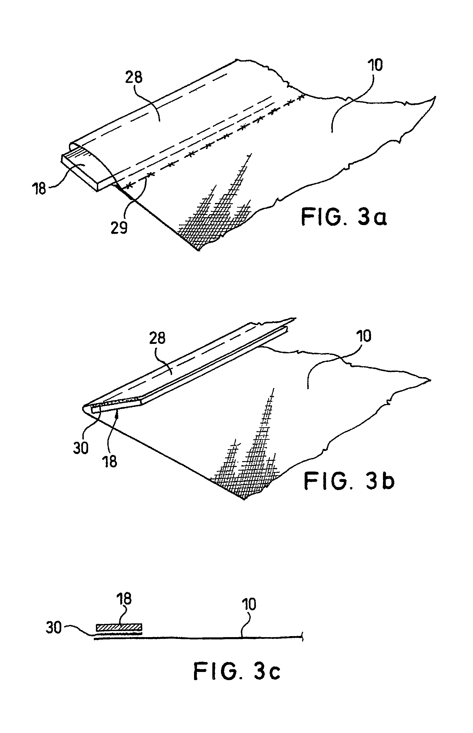
[0050]FIG. 1 shows a shade arrangement in accordance with the invention with a shade length 10 which can be wound and unwound from a roller tube 12 and thus can be moved along two guides 20. The roller tube 12 is pivotally mounted by means of body-mounted bearings 14 and on the end of the shade length 10 facing away from the roller tube the shade length is attached to a pull 16. On either side of the shade length 10, a respective guide strip 18 is guided in the guides 20 and is connected to the shade length and wound together with it onto the roller tube 12. The guide strips 18 are guided on both sides in the guides 20 such that the shade length 10, but not the two guide strips 18, can emerge from the guide 20 through an opening of the guides 20. At a corresponding distance of the two guides 20, on the two side edges of the shade length 20 compared to the width of the shade length, the latter can itself be tensioned transversely to its drawing direction, such that, for example, flut...


PUM


Abstract

A shade arrangement for a motor vehicle with at least one shade length and at least one roller tube for taking-up and unrolling the shade length, each side edge of the shade length having at least one flexible, flat guide strip which extends along the drawing direction of the shade and is guided in a guide. The guide contains a connecting link in which the guide strip is guided, and which has an exit gap through which the shade length emerges from the guide, the guide strip being guided such that its base surface is guided essentially parallel to the adjacent region of the shade length. The shaping and dimensioning of the exit gap and guide strip are such that the guide strip cannot emerge from the guide by itself. The shade length is connected to the roller tube via at least one constant force spring.

Description

BACKGROUND OF THE INVENTION[0001]1. Field of the Invention[0002]This invention relates to shade arrangements for a motor vehicle with at least one shade length and at least one roller tube for taking-up and unrolling the shade length, the shade length being guided along its side edge regions by at least one flexible, flat guide strip which extends along the drawing direction of the shade and is guided in a guide.[0003]2. Description of Related Art[0004]Shade arrangements for use in automotive construction are used, for example, as sun protection under a transparent vehicle body surface or also as a cover for the trunk space in a station wagon. These arrangements generally consist of a shade length which on its one end is wound onto a roller tube and which is tensioned by the reset force of the roller tube. The other end of the shade length is conventionally attached to a pull which can be moved by an electric drive or by hand, by which the shade length is accordingly drawn or rewoun...

Claims


Application Information

Patent Timeline
Patent Type & Authority Patents(United States)
IPC IPC(8): A47G5/02E06B9/56B60J1/20B60J3/00B60J11/00B60J7/00B60R5/04
CPCB60J7/0015B60J1/2041B60J1/2044B60J1/2052B60R5/047
Inventor GLASL, SEBASTIANADLHOCH, CHRISTIANSCHULZ, HORST-MARTINHIRSCHVOGEL, ENGELBERTBERGMILLER, ALEXANDEROERKE, PHILIP
Owner WEBASTO AG
Learn More