
Surgical template for performing dental implantology

Active Publication Date: 2015-02-17
SWISSMEDA AG
View PDF9 Cites 13 Cited by
  • Summary
  • Abstract
  • Description
  • Claims
  • Application Information

AI Technical Summary

Benefits of technology

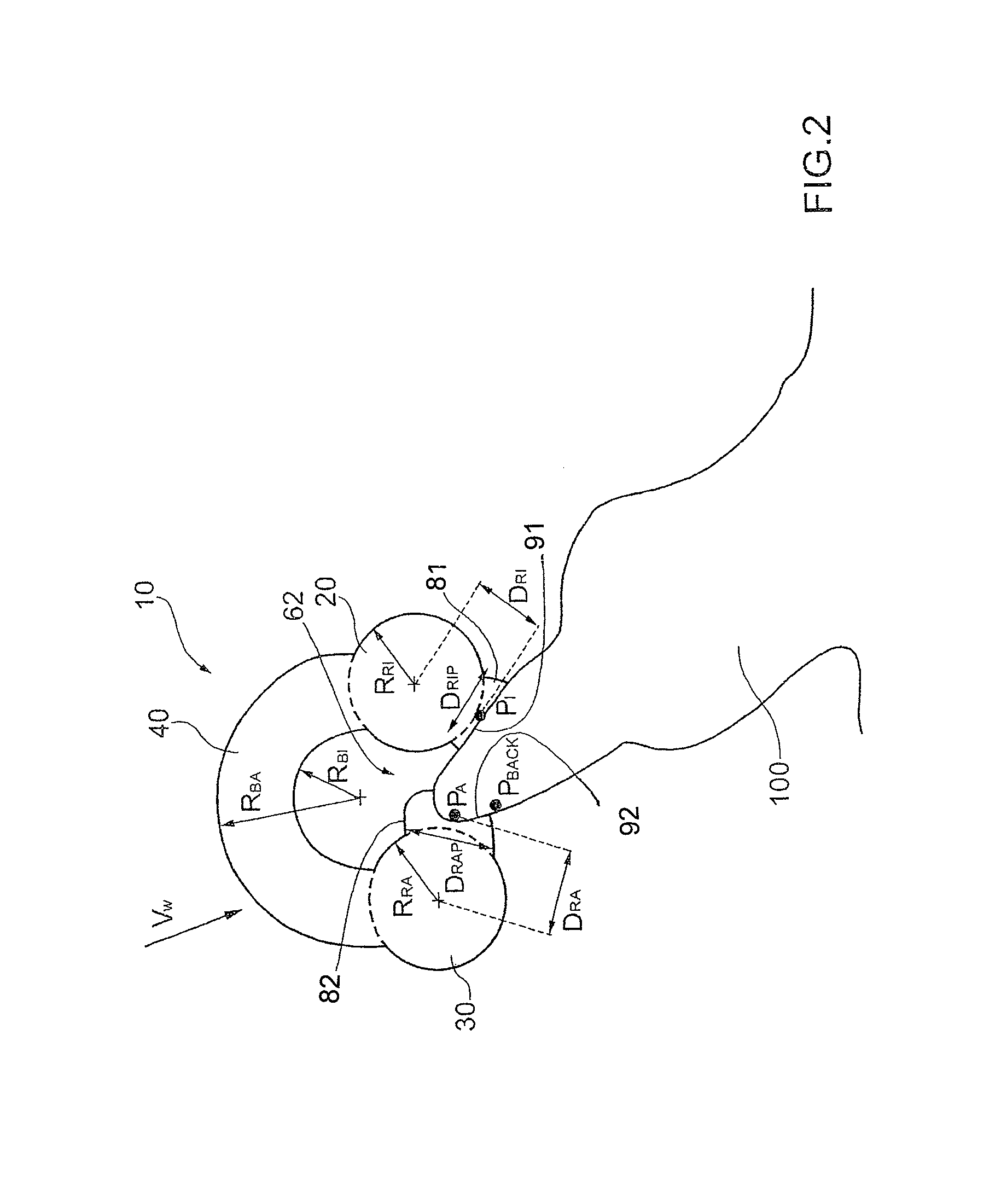
[0013]It is a preferred advantage of the invention that all outer connecting points are positioned such that there is no material of any connecting point beyond an undercut plan being the plan perpendicular to the predefined placement direction of the template onto the dental apparatus of the patient in his oral cavity. This ensures that the template cannot become stuck onto the dental apparatus.
[0014]Furthermore, it is preferred that there is at least one holder attached on the underside of the outer rail having a sufficient predefined free length to allow a clipping action in the area beyond the undercut plan onto the dental apparatus of the patient in his oral cavity to hold the template resiliently in place.
[0015]The webs connecting the rails are provided as part of a full material torus or spline body, especially a hermite spline body, attached or unitarily formed on the upper portion of the rails and preferably having a main orientational axis being in line with the main longitudinal axis of the adjacent portions of the rails.
[0016]Beside the webs connecting the rails one with another a stiffening connector can be provided between the opposite free ends of the inner rail to provide a lightweight but stiff and sturdy template.
[0017]In the case of an embodiment having only one complete rail and optionally additionally a part second rail, the complete rail is preferably the inner rail; therefore the connecting webs in this case are connecting the inner rail with the outer (second) contact points, wherein contact points mean contact point portions, since the method creates 3D model data with predetermined interfaces being represented through middle points of calculated volume spline functions.
[0018]The template can comprise an end connector provided at the free end of the rails or at a terminal guide ring. Said end connector attaches a soft tissue support having a bottom surface adapted to be complimentary to an area of soft tissue of a patient to be used as support surface.

Problems solved by technology

One important issue relating to providing a template in one single step without the necessity to rework the template to a great extent is related to the absence of undercuts.

Method used


Image

  • Surgical template for performing dental implantology
  • Surgical template for performing dental implantology
  • Surgical template for performing dental implantology

Examples


Embodiment Construction

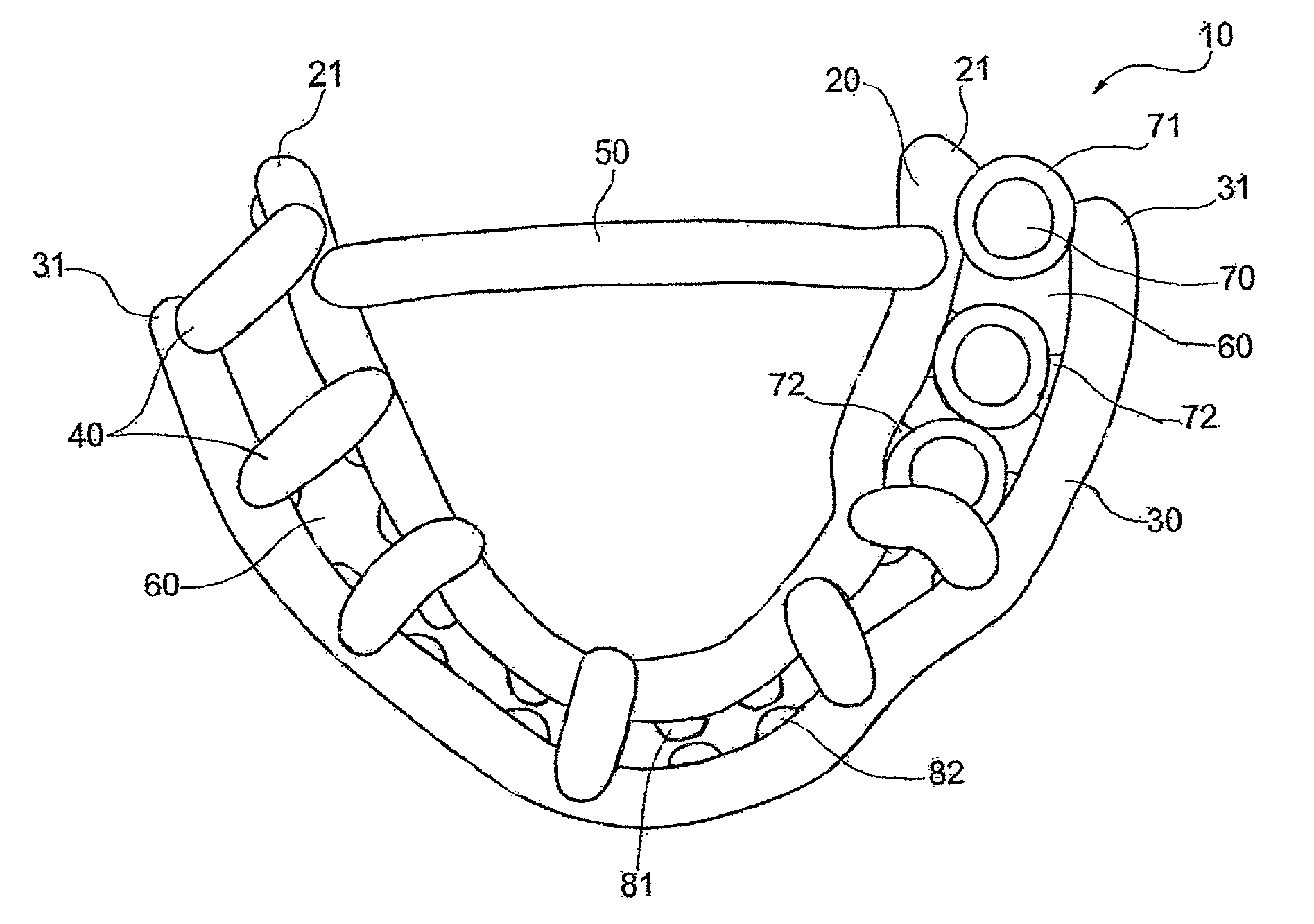
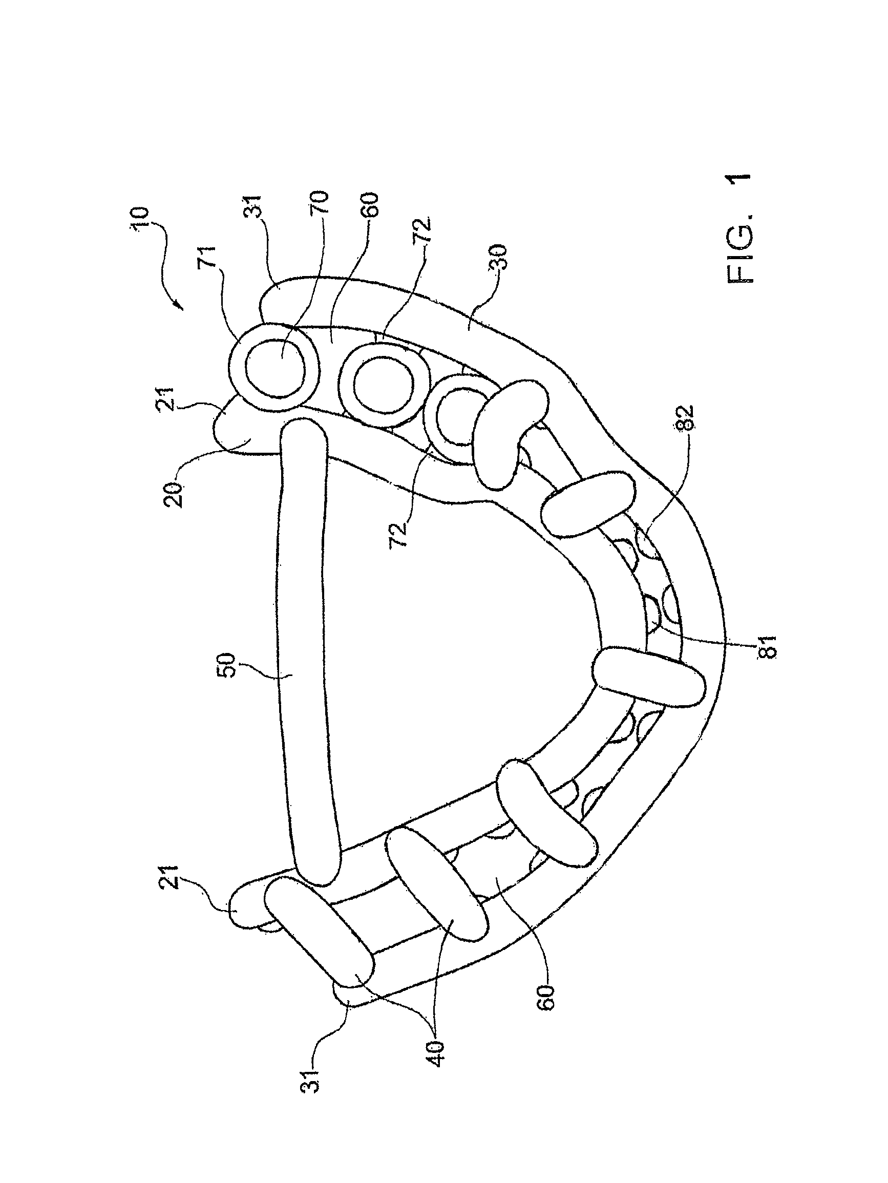
[0033]FIG. 1 shows a schematic view from above on a template 10 for a lower jaw according to an embodiment of the invention. Within this embodiment template 10 comprises a complete inner rail 20 and a complete outer rail 30. These rails 20 and 30 are in the embodiment shown made of a plastic material, especially through rapid-prototyping, and the rails 20 or 30 comprise in a cross-section an essentially regular and constant diameter which is based on a cylindrical curved rod. The rails 20 and 30 are preferably made of solid material having such a circular cross-section but they might be made at least partially hollow and the outer circumference in a cross-section can also be e.g. elliptical. In fact, the rails 20 and 30 appear as full-material tubes. Beside rapid prototyping for transferring 3D model data into the geometry of the template 10 it is also possible to use machining procedures as milling, based on a plastics material or another different basic material. The template 10 c...


PUM

PropertyMeasurementUnit
distanceaaaaaaaaaa
lengthaaaaaaaaaa
areaaaaaaaaaaa

Abstract

A surgical template (10) comprises at least one a drill guide bore (70) surrounded by a guide bore ring (71) and is adapted to be positioned within the oral cavity of patient. The template (10) comprises an inner rail (20) and an outer rail (30) with an interspace (60) in between. At least three inner and three outer connecting points (81, 82) are provided on the inner and outer rail (20, 30) which are adapted to be positioned on portions of the dental apparatus of the patient in his oral cavity to define the three dimensional position and orientation of the at least one drill guide bore ring (71). The rails (20 and 30) are provided in a predetermined varying distance one from the other allowing accommodation of the inner and outer connecting points (81 and 82) on the rails (20, 30), wherein the template (10) further comprises at least two connecting webs (40) connecting the inner rail (20) and the outer rail (30) in a predetermined distance one from the other.

Description

TECHNICAL FIELD[0001]The present invention relates to a surgical template for performing dental implantology, comprising at least one a drill guide bore surrounded by a guide bore ring, as well as a method for providing such a template.PRIOR ART[0002]From prior art a number of methods are known for manufacturing a template for providing dental implants in a jaw of a patient, especially human patients.[0003]In dental surgery such implants are provided in a jaw to anchor dental prostheses. Such a prosthesis comprises one single false tooth or a superstructure onto which several teeth are provided.[0004]It is always the aim of the prior art to improve the steps which have to be provided until the prosthesis can be applied to a patient. One of the important steps is drilling holes in the bone of the jaw, for which a template is to be provided.[0005]One method and template is known from WO 2011 / 143725 within which a template is manufactured on the basis of a plurality of generated three-...

Claims


Application Information

Patent Timeline
Patent Type & Authority Patents(United States)
IPC IPC(8): A61C1/08A61C8/00
CPCA61C8/009A61C1/082A61C1/084Y10T29/49567
Inventor SCHMALZLE, STEFANDANZBERG, JORG
Owner SWISSMEDA AG
Learn More