
Minimally invasive retractor and posted screw

a technology of retractor and post screw, which is applied in the field of orthopedic spine surgery, can solve the problems of cumbersome devices, unfavorable minimally invasive approaches, and poor adaptability of procedures, and achieve the effect of convenient further the retractor blade, and reliable securing of the screw

Active Publication Date: 2015-02-17
K2M
View PDF52 Cites 1 Cited by
  • Summary
  • Abstract
  • Description
  • Claims
  • Application Information

AI Technical Summary

Benefits of technology

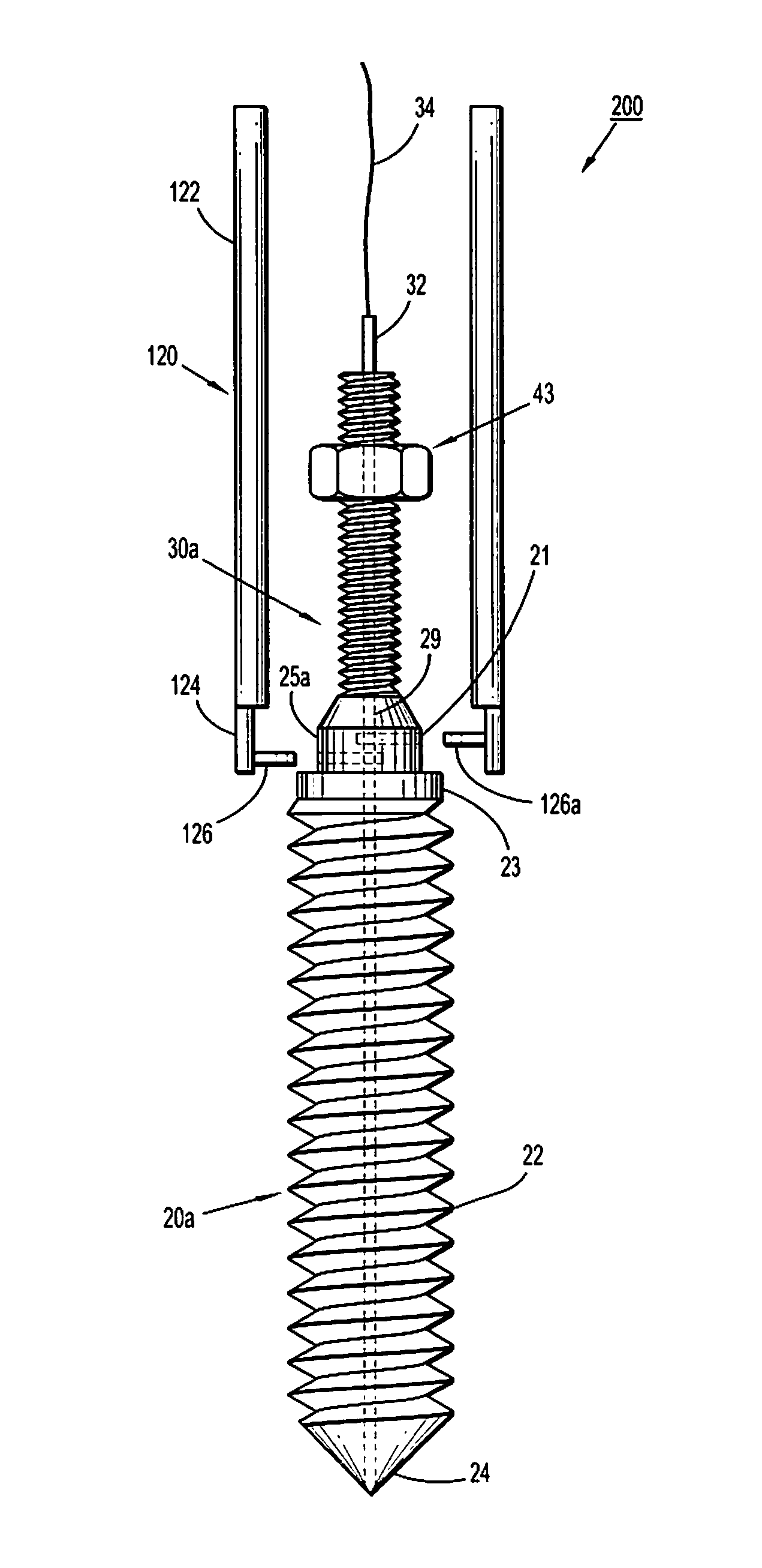
The patent text describes a screw that is used in a retractor. The screw is designed to fit snugly into the retractor, ensuring that it is secure. The screw and retractor are securely attached to each other using protrusions and grooves on the blades of the retractor. The screw may also be overmolded onto the retractor blades. The technical effect of this design is that it provides a reliable and secure attachment between the screw and the retractor, ensuring the proper functionality of the device.

Problems solved by technology

These devices tend to be cumbersome and are not well adapted for use in small incisions.
Typical retractors are also positioned into the soil tissue and are levered back to hold the wound open, frequently requiring re-positioning if they dislodge, obstruct the physician's view, or interfere with access to the surgical site.
This procedure is not generally conducive to a minimally invasive approach.
For example, difficulty arises upon the introduction of a length of rod into a very small incision with extremely limited access and visibility.
Most spine implant procedures are open procedures, and while many manufacturers advertise a minimally invasive method, the procedure is typically not recommended for fusions and focus on more common and accepted minimally invasive spine procedures such as kyphoplasty, vertebroplasty, and discectomy.
For these reasons, the surgeon cannot access the surrounding anatomy for complete preparation of the field.
Nor does SEXTANT® allow for any variation in the procedure, if need be.
This system is less complicated than the SEXTANT® only requiring two incisions for a unilateral, one-level fusion, but it is limited in the same way as the SEXTANT® because it also requires the instrumentation to be rigidly fixed to the pedicle screw.
While they have advantages over a general “open” procedure, they do not provide all of the advantages of a truly minimally invasive approach.
Their characterization as “minimally open” procedures is a result of the inherent difficulty of introducing a rod in a minimally invasive spinal procedure.
In order to introduce a rod long enough to accomplish a single level fusion, these systems describe an incision long enough to accept such a rod, thereby undermining the advantages of a minimally invasive approach.
The problem of rod introduction warrants further discussion as it is the central problem in minimally invasive spinal fusions.

Method used


Image

  • Minimally invasive retractor and posted screw
  • Minimally invasive retractor and posted screw
  • Minimally invasive retractor and posted screw

Examples


first embodiment

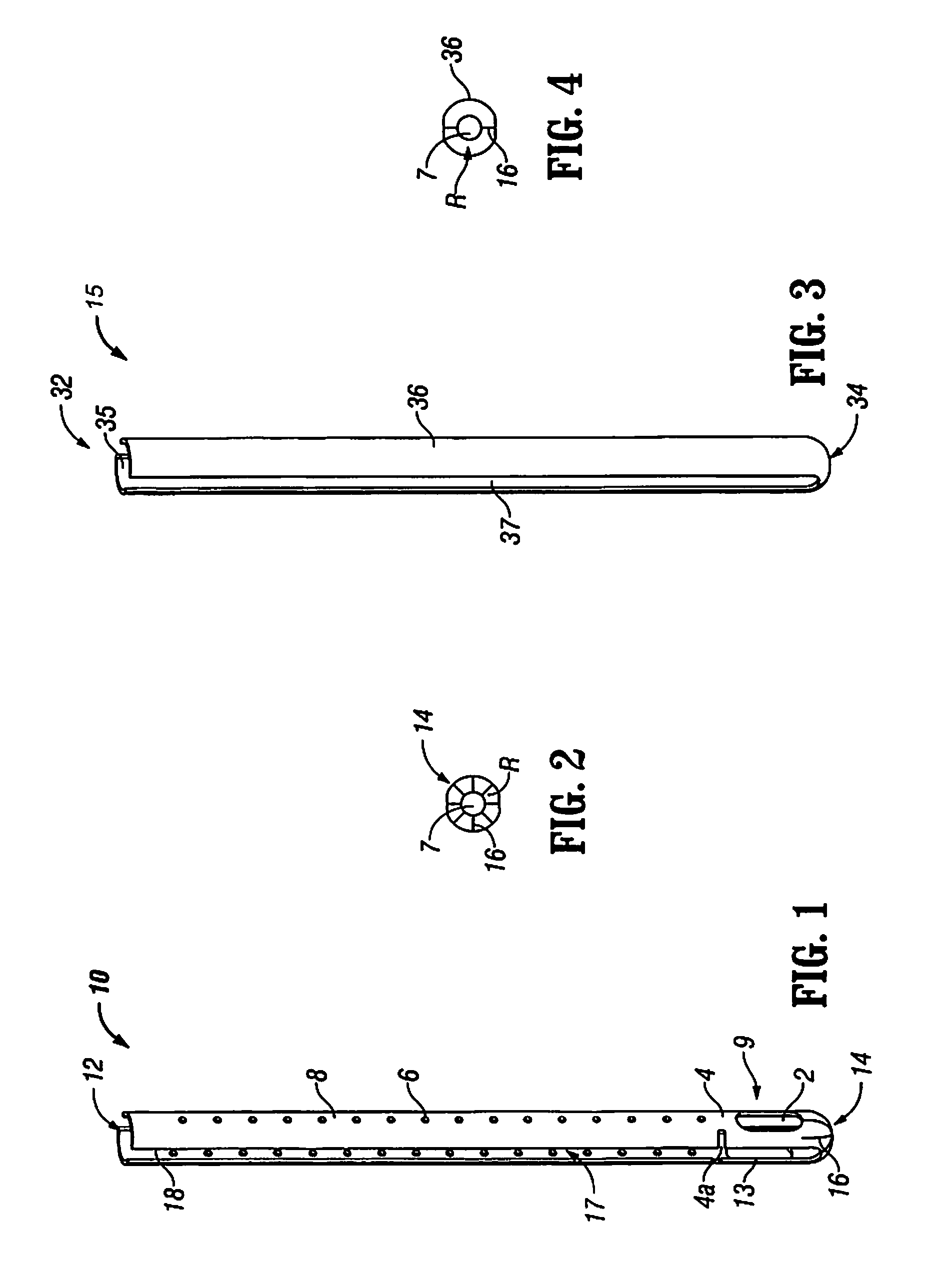
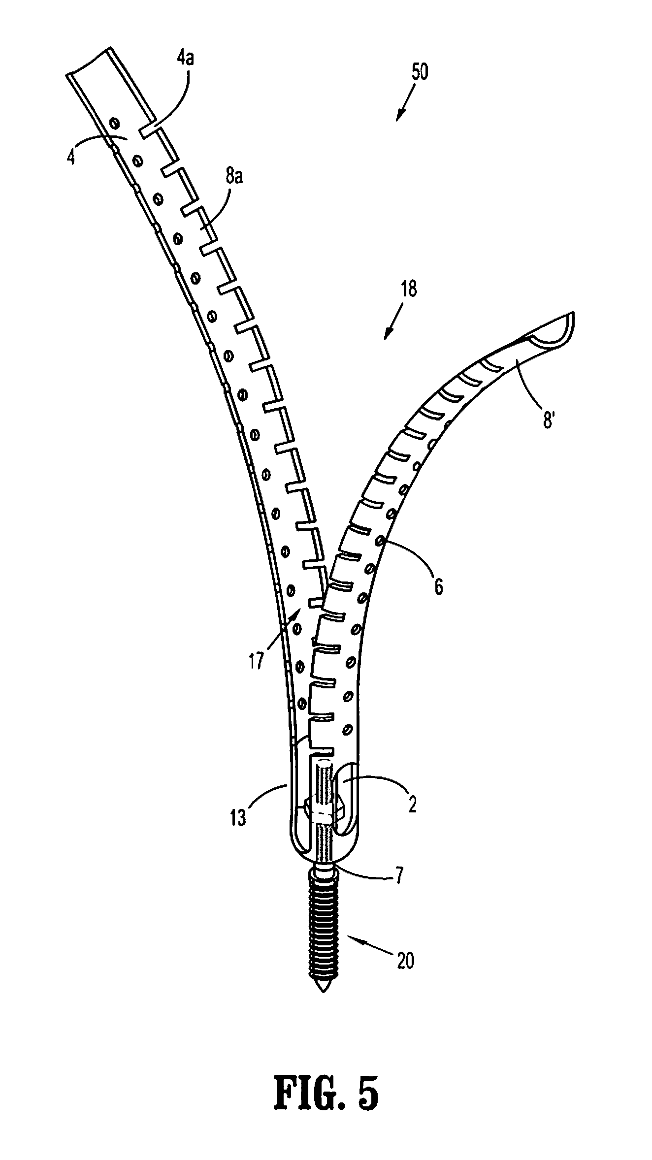
[0062]Referring initially to FIGS. 1 and 2, the presently disclosed minimally invasive retractor is illustrated and generally designated as 10. Retractor 10 includes an open proximal end 12 and a distal end 14. In addition, retractor 10 includes a pair of retractor blades 8 having a plurality of instrument holes 6 disposed on each of retractor blades 8. Instrument holes 6 are configured and dimensioned to cooperate with different surgical instruments as will be discussed in detail hereinafter. A distal region 9 of retractor 10 includes an opening 7 (FIG. 2), at least one slot or window 2, and a pair of arms 13 extending from distal end 14 to a flexible region or living hinge 4. Window 2 is sized and configured to receive instruments therethrough. Each retractor blade 8 is attached to living hinge 4 to define a substantially continuous elongate member. A pair of recesses 4a is formed between retractor blade 8 and arm 13 to define living hinge 4.

[0063]Distal end 14 optionally may incl...

second embodiment

[0067]Referring now to FIGS. 3 and 4, the present disclosure is illustrated as retractor 15 having an open proximal end 32 and a distal end 34. Retractor 15 includes a pair of retractor blades 36. Similar to retractor 10, distal end 34 is adapted to mate with a threaded shank of a posted pedicle screw. Additionally, retractor 15 includes an opening 7 (FIG. 4) that is substantially identical to opening 7 of retractor 10. As in the previous embodiment, blades 36 have an arcuate configuration that is less than about 180° and are radially spaced apart to define a continuous slot 37 along a substantial portion of retractor 15.

[0068]Furthermore, retractor blades 36 define a passage 35 through retractor 15. In this embodiment, retractor blades 36 are also flexible, but bend radially outwards from a centerline of retractor 15 near relief regions R (FIG. 4). As in the previous embodiment, relief regions R defined by slits 16 (shown as a pair of slits in FIG. 4) as previously discussed in con...


PUM


Abstract

A minimally invasive retractor assembly includes a posted screw and one or more retractor blades. Each retractor blade is releasably coupled to the posted screw. The retractor blade or blades are manipulated or flexed relative to the posted screw allowing retraction of tissue surrounding the incision. The retractor is made of a biocompatible material, sterile packaged and disposable after one use. A system and method for using the retractor and performing a minimally invasive spine surgical procedure are also disclosed.

Description

BACKGROUND[0001]1. Technical Field[0002]This invention relates generally to orthopedic spine surgery and in particular to a minimally invasive retractor with a posted screw and methods for use in a minimally invasive surgical procedure.[0003]2. Description of Related Art[0004]There has been considerable development of retractors and retractor systems that are adapted for use in less invasive procedures. Many of the recent developments are based on traditional types of surgical retractors for open procedures, predominantly table-mounted devices of various designs. These devices tend to be cumbersome and are not well adapted for use in small incisions. Standard hand-held surgical retractors are well known and can be modified to fit the contours of these small incisions, but they require manual manipulation to maintain a desired placement, thereby occupying one hand of the physician or requiring another person to assist the physician during the procedure. Typical retractors are also po...

Claims


Application Information

Patent Timeline
Patent Type & Authority Patents(United States)
IPC IPC(8): A61B1/32
CPCA61B1/32
Inventor GOREK, JOSEFWOODS, RICHARD W.
Owner K2M
Learn More