Dual-shaft synchronous movement device

a synchronous movement and dual-shaft technology, applied in the direction of instruments, details of portable computers, gearing, etc., can solve the problems of wires falling off the rollers, wires are likely to slip or up and down deflect from the rollers, and the delay of kinetic energy transmission will occur

Active Publication Date: 2015-02-24
FIRST DOME
View PDF26 Cites 18 Cited by
  • Summary
  • Abstract
  • Description
  • Claims
  • Application Information

AI Technical Summary

Benefits of technology

[0014]It is therefore a primary object of the present invention to provide a dual-shaft synchronous movement device includes a first shaft and a second shaft, which are synchronously rotatable. The synchronous movement device further includes a first rotor and / or a third rotor disposed on the first shaft and a second rotor and / or a fourth rotor disposed on the second shaft, and an inextensible / non-contractible flexible plate connected between the first (or the third rotor) and the second rotor (or the fourth rotor). When the first shaft drives the first rotor (or the third rotor) to rotate, the inextensible / non-contractible flexible plate pulls the second rotor (or the fourth rotor) to rotate in a direction reverse to a moving direction of the first rotor so as to make the first and second shafts synchronously rotate. The synchronous movement device solves the problem of delay of kinetic energy transmission and the problem of slippage, deflection and untrue operation of the conventional device.

Problems solved by technology

As known by those who are skilled in this field, during the operation process of the wires or the transmission belts, delay of kinetic energy transmission will take place.
This is because the wires contact the rollers by points or lines or there is a gap between the wires and the rollers so that the wires are likely to slip or up and down deflect from the rollers.
Under such circumstance, the wires will untruly operate to cause error.
Also, the wires are made of elastic material and the fixing structure for assembling the wires with the rollers is not ideal.
In this case, the transmission effect of the wires will be deteriorated and the wires may detach from the rollers.
Especially, after a period of use, the force of the wires, which is preset in the assembling process will decrease due to elastic failure.
Under such circumstance, the synchronous movement effect of the transmission mechanism will be deteriorated.
There is another problem existing in the application and manufacturing of the wires.
This will make it more difficult to control the quality of wiring and assembling.
As a result, the manufacturing cost is increased.
However, as known by those who are skilled in this field, with the transmission gears, the gap between the shafts of the dual-shaft synchronous movement device can be hardly minified.
Therefore, the entire transmission unit or structure will occupy a considerably large space.
Especially, when the transmission unit is applied to a notebook or a miniaturized electronic device, the electronic device can hardly meet the requirement for lightweight and slimmed design.

Method used


Image

  • Dual-shaft synchronous movement device
  • Dual-shaft synchronous movement device
  • Dual-shaft synchronous movement device

Examples


Embodiment Construction

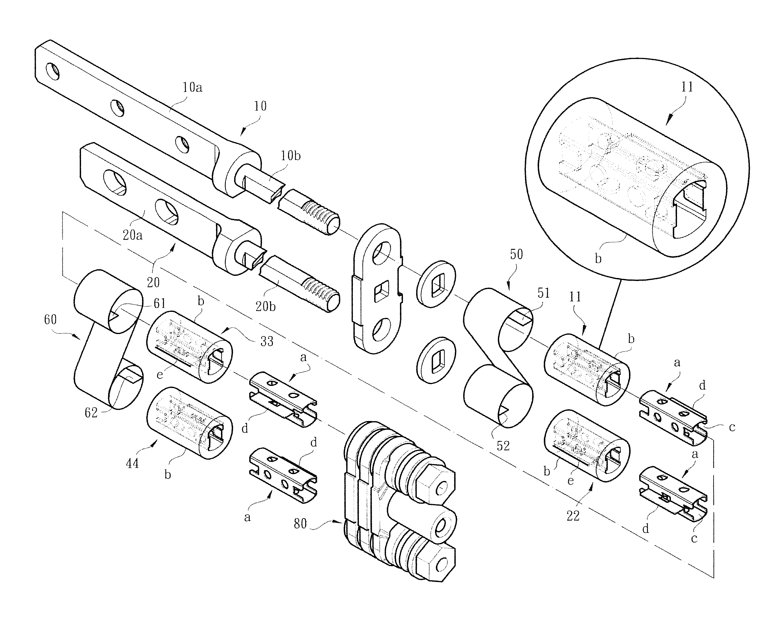
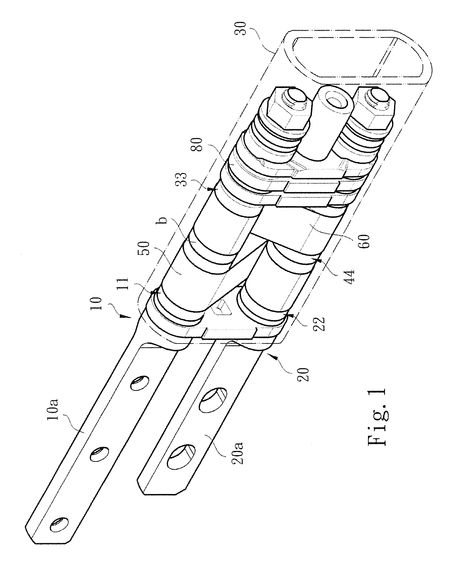
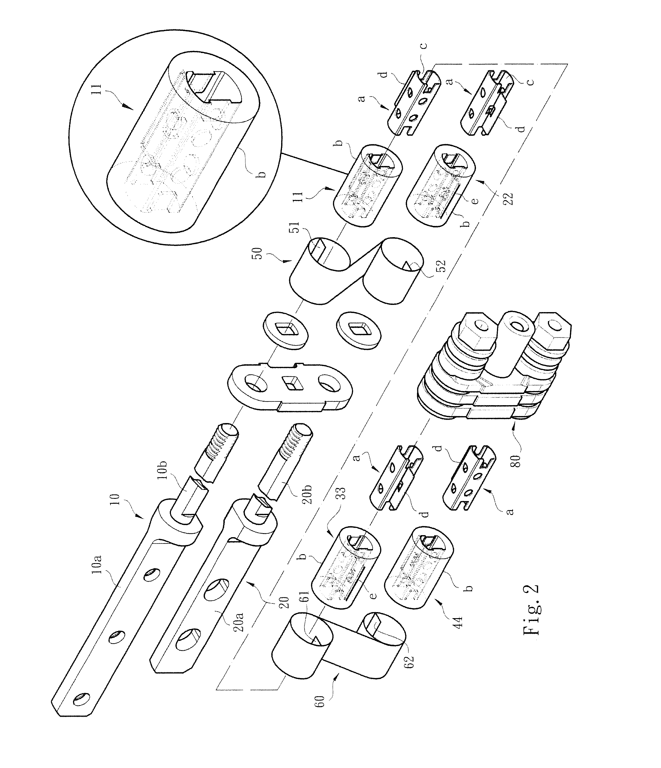
[0025]Please refer to FIGS. 1, 2 and 3. The dual-shaft synchronous movement device of the present invention includes a first shaft 10 and a second shaft 20. The first and second shafts 10, 20 are assembled with each other and disposed in a casing 30. Each of the first and second shafts 10, 20 has a fixed end 10a, 20a and a pivoted end 10b, 20b. Through fixing seats (not shown), the fixed ends 10a, 20a of the first and second shafts 10, 20 are respectively fixed on a display module 91 and an apparatus body module 92 of an electronic apparatus 90 (such as a mobile phone or a computer).

[0026]Referring to FIGS. 1 and 2, the pivoted end 10b of the first shaft 10 is provided with a first rotor 11 (and / or a third rotor 33) and the pivoted end 20b of the second shaft 20 is provided with a second rotor 22 (and / or a fourth rotor 44). Inextensible / non-contractible flexible plates 50 (and / or 60) are disposed between the first and second rotors 11, 22 (and / or the third and fourth rotors 33, 44)....


PUM


Abstract

A dual-shaft synchronous movement device includes a first shaft and a second shaft, which are synchronously rotatable. The synchronous movement device further includes a first rotor and / or a third rotor disposed on the first shaft and a second rotor and / or a fourth rotor disposed on the second shaft, and an inextensible / non-contractible flexible plate connected between the first (or the third rotor) and the second rotor (or the fourth rotor). When the first shaft drives the first rotor (or the third rotor) to rotate, the inextensible / non-contractible flexible plate pulls the second rotor (or the fourth rotor) to rotate in a direction reverse to a moving direction of the first rotor so as to make the first and second shafts synchronously rotate. The synchronous movement device solves the problem of delay of kinetic energy transmission and the problem of slippage, deflection and untrue operation of the conventional device.

Description

BACKGROUND OF THE INVENTION[0001]1. Field of the Invention[0002]The present invention relates to an improved dual-shaft synchronous movement device. The dual-shaft synchronous movement device includes a first shaft and a second shaft and an assembly of rotors and cooperative inextensible / non-contractible flexible plates wound on the rotors. In operation, the first and second shafts are synchronously rotated to overcome the problem of the conventional transmission mechanism that the wires are likely to slip or deflect from the rollers.[0003]2. Description of the Related Art[0004]There are various electronic apparatuses provided with covers or display screens or viewers, such as mobile phones, notebooks, PDA, digital imagers and electronic books. The covers or display screens or viewers are pivotally mounted on the electronic apparatuses via pivot pins or rotary shafts, whereby the covers or display screens or viewers can be freely rotated and opened / closed under external force.[0005]...

Claims


Application Information

Patent Timeline
Patent Type & Authority Patents(United States)
IPC IPC(8): E05D7/00E05D11/08F16H19/08F16H21/44
CPCF16H21/44E05Y2900/606G06F1/1618G06F1/1681Y10T74/18856
Inventor HSU, AN SZU
Owner FIRST DOME
Why Eureka
Try Eureka