
Slide cover linking mechanism with both push aid effect and end buffering effect

a technology of push aid and slide cover, which is applied in the direction of mechanical equipment, electrical apparatus construction details, casings/cabinets/drawers, etc., can solve the problems of frequent impact of slide cover, violent deceleration, and only very short buffering travel of elastic elements

Active Publication Date: 2015-03-17
FIRST DOME
View PDF4 Cites 0 Cited by
  • Summary
  • Abstract
  • Description
  • Claims
  • Application Information

AI Technical Summary

Benefits of technology

[0006]It is therefore a primary object of the present invention to provide a slide cover linking mechanism with both push aid effect and end buffering effect. The slide cover linking mechanism is applicable to large-size electronic product for driving the slide cover thereof.
[0007]At the end of the opening / closing travel of the slide cover, the slide cover linking mechanism can provide a buffering effect to avoid impact to the slide cover due to excessively great driving force and instantaneous change thereof. Therefore, the possibility of damage to relevant components can be minimized.
[0008]It is a further object of the present invention to provide the above slide cover linking mechanism with both push aid effect and end buffering effect. With the slide cover linking mechanism, the slide cover can be more smoothly opened / closed to promote competitive ability of the product.

Problems solved by technology

However, there are only few patents for providing buffering or damping effect at the final stage of the sliding travel.
Such elastic elements only provide very short buffering travel.
As a result, at the final stage of the opening / closing travel of the slide cover, a violent deceleration is likely to take place.
Under such circumstance, the slide cover is frequently impacted.
This will affect the assembling stability of the relevant components or even lead to damage to the components.
However, the structure also acts as an obstacle to the drive of the slide cover.
Therefore, the user can hardly conveniently use the electronic product.

Method used


Image

  • Slide cover linking mechanism with both push aid effect and end buffering effect
  • Slide cover linking mechanism with both push aid effect and end buffering effect
  • Slide cover linking mechanism with both push aid effect and end buffering effect

Examples


Embodiment Construction

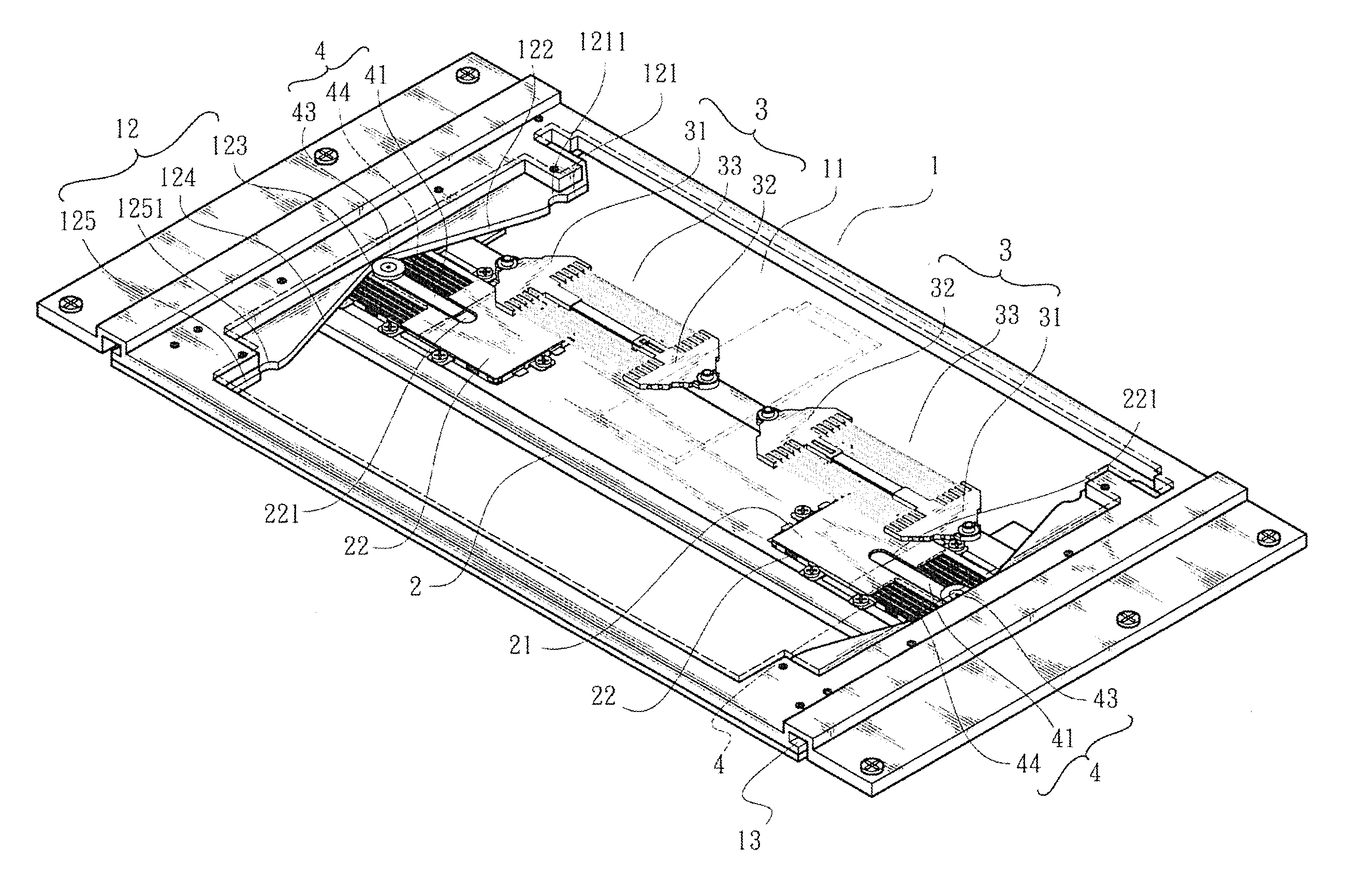
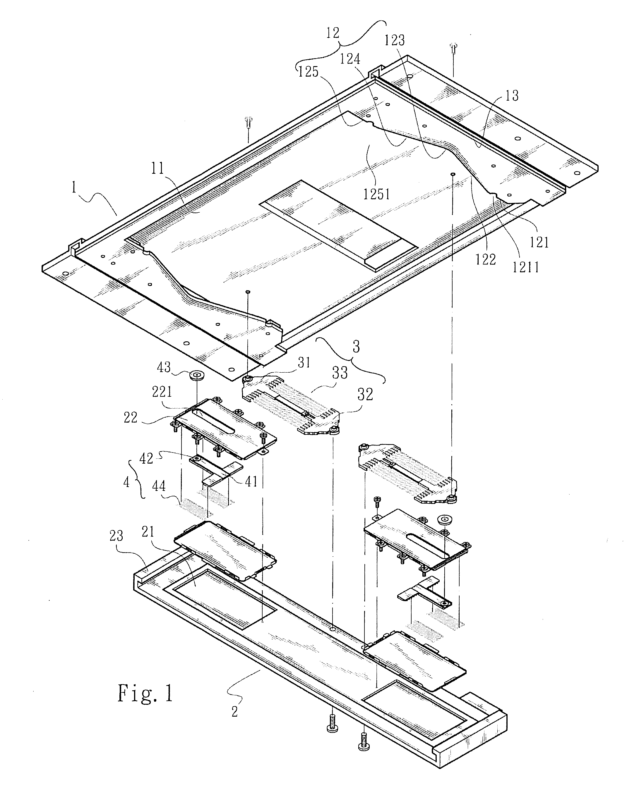
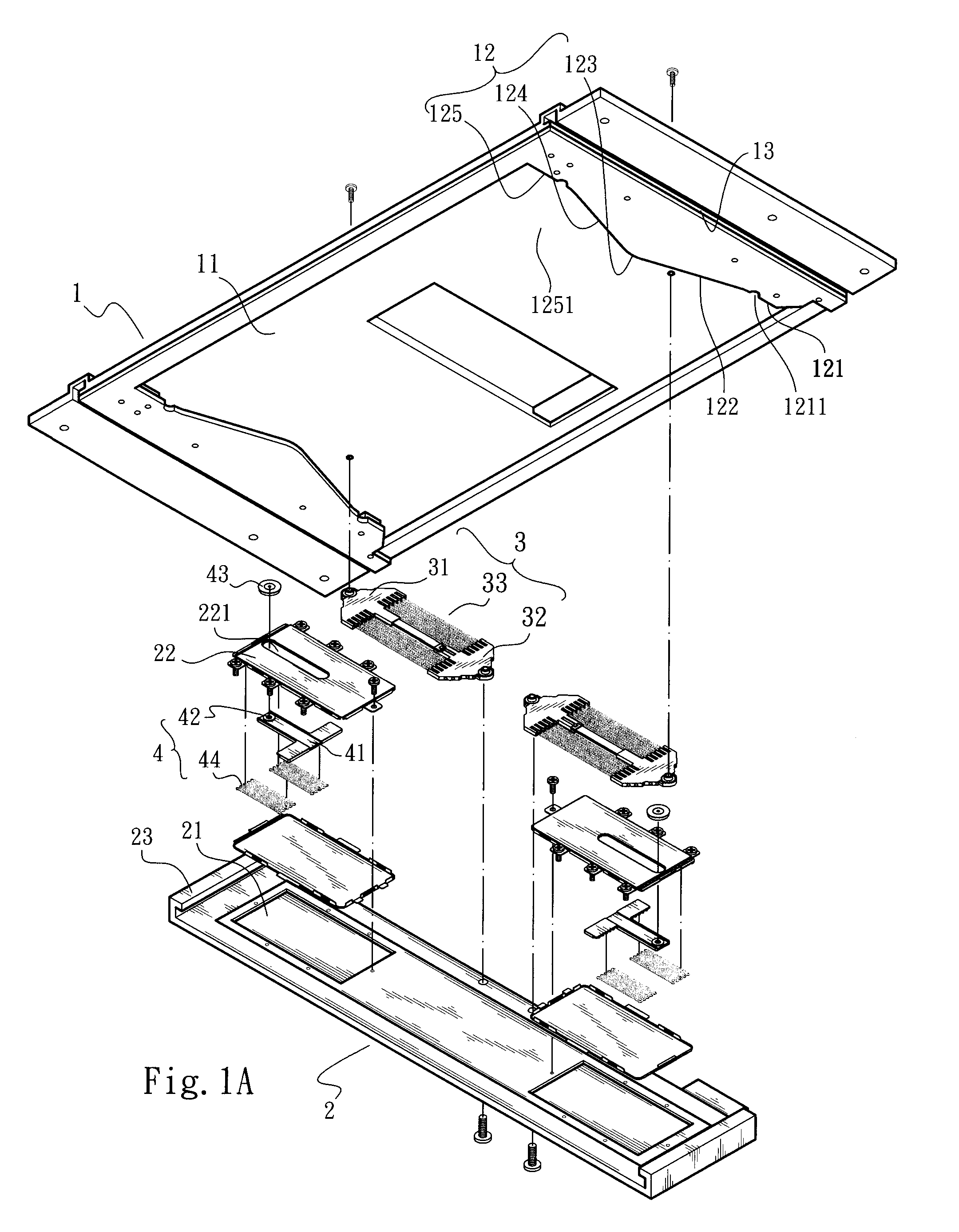
[0024]Please refer to FIGS. 1 to 3. The present invention includes a seat body 1, a slide seat 2, a first elastic member 3 and a second elastic member 4. The seat body 1 is formed with a receiving space 11 and at least one first slide guide section 13. At least one second slide guide section 12 is disposed in the receiving space 11. According to a preferred embodiment as shown in the drawings, two first slide guide sections 13, (which can be recessed slide channels), are disposed on two sides of the receiving space 11. The first slide guide sections 13 extend in parallel to each other. In addition, two second slide guide sections 12 are respectively disposed on two sides of the receiving space 11. The second slide guide sections 12 can be transverse lateral guide rails. A turning section 123 is disposed at the middle of at least one of the second slide guide sections 12. In the drawings, the turning section 123 has the form of a gradually turning section. Due to the turning sections...


PUM


Abstract

A slide cover linking mechanism with both push aid effect and end buffering effect includes: a seat body having a receiving space and at least one first slide guide section, at least one second slide guide section with a middle turning section being disposed in the receiving space; a slide seat slidable along the first slide guide sections and formed with a receiving recess in which a third slide guide section is disposed; at least one first elastic member two ends of which are respectively pivotally connected in the receiving space and with a middle section of the slide seat; and at least one second elastic member two ends of which are respectively connected in the receiving recess and with a slide guide member slidable within the third slide guide section. A movable member movable along the second slide guide section is pivotally connected on the slide guide member.

Description

BACKGROUND OF THE INVENTION[0001]1. Field of the Invention[0002]The present invention relates generally to a slide cover linking mechanism with both push aid effect and end buffering effect, and more particularly to a slide cover linking mechanism, which provides a push strength saving and slide buffering / protection effect.[0003]2. Description of the Related Art[0004]Following the rapid advance of various portable electronic products, all kinds of slide cover linking structures have been continuously developed. For example, Taiwanese Patent Publication No. I208031 discloses a slide cover device, Publication No. M297113 discloses a slidable pivot device, and Publication No. M379940 discloses an elastic unit of slide cover device. These patents provide slide cover linking structures for easily pushing the slide covers to semiautomatically open / close the slide covers. However, there are only few patents for providing buffering or damping effect at the final stage of the sliding travel....

Claims


Application Information

Patent Timeline
Patent Type & Authority Patents(United States)
IPC IPC(8): F16C29/00H04M1/02
CPCH04M1/0237
Inventor MAI, CHIEN CHENGDAI, WAY HANTSAI, CHIEN NAN
Owner FIRST DOME
Learn More