Anchor bolt, anchor, connecting nut and clamping nut

a technology of connecting nut and clamping nut, which is applied in the direction of load-modifying fasteners, screws, fastening means, etc., can solve the problems of greater distance between the eyes of the worker and the anchor, the anchor disclosed in the patent literature 1 is not suitable for fixing to the ceiling structure, and the integration of the tip portion of the steel bar with the tip portion of the steel bar. the effect of the spreading sleeve and the ceiling structur

Active Publication Date: 2015-03-17
ENUPATTO
View PDF45 Cites 8 Cited by
  • Summary
  • Abstract
  • Description
  • Claims
  • Application Information

AI Technical Summary

Benefits of technology

[0011]The worker relies heavily on his experience for management of the rotation torque. This easily causes unevenness of the placing quality of anchors, while making it difficult to find faulty placement even if it is generated.
[0013]The present invention has been made to solve the aforementioned problems. It is an object of the present invention to provide an anchor bolt, an anchor, a connecting nut and a clumping nut that make check of the placement condition of the anchor easy to realize efficient and safe check after the placement of the anchor.
[0018]The cap member preferably includes a wall section contacted by an inner side surface of the attachment hole in the breaking groove. In this structure, the wall section of the cap member presses the broken portion from inside when the breaking groove is broken. This structure prevents unnecessary breaking projection to be created.
[0034]The clamping nut described above further includes a cap member set in the circular hole. The cap member includes a wall section contacted by an inner side surface of the circular hole in the breaking groove. The breaking in the breaking groove preferably causes the cap member to be removed from the metal member together with the one end portion between the one end surface and the breaking groove. In this structure, the wall section of the cap member presses the broken portion from inside when the breaking groove is broken. This structure prevents unnecessary breaking projection to be created.
[0037]The present invention makes it possible to check the placement condition of the anchor by visually checking whether or not the breaking groove is broken to realize efficient and safe check after the placement.

Problems solved by technology

The anchor disclosed in patent literature 1 is not suited for fixation to a ceiling structure.
So, if the ceiling structure is shaken strongly for example by an earthquake, the cone nut falls off the inside of the spreading sleeve, resulting in a fear of drop of the spreading sleeve integrated with the tip portion of the steel bar from the ceiling structure.
This process generates a problem as one cannot check to see visually if the head has caused the anchor socket to spread to its normal placement condition.
This placement process makes a distance between the eyes of the worker and the anchor greater, so visual check is made more difficult.
This easily causes unevenness of the placing quality of anchors, while making it difficult to find faulty placement even if it is generated.

Method used


Image

  • Anchor bolt, anchor, connecting nut and clamping nut
  • Anchor bolt, anchor, connecting nut and clamping nut
  • Anchor bolt, anchor, connecting nut and clamping nut

Examples


first preferred embodiment

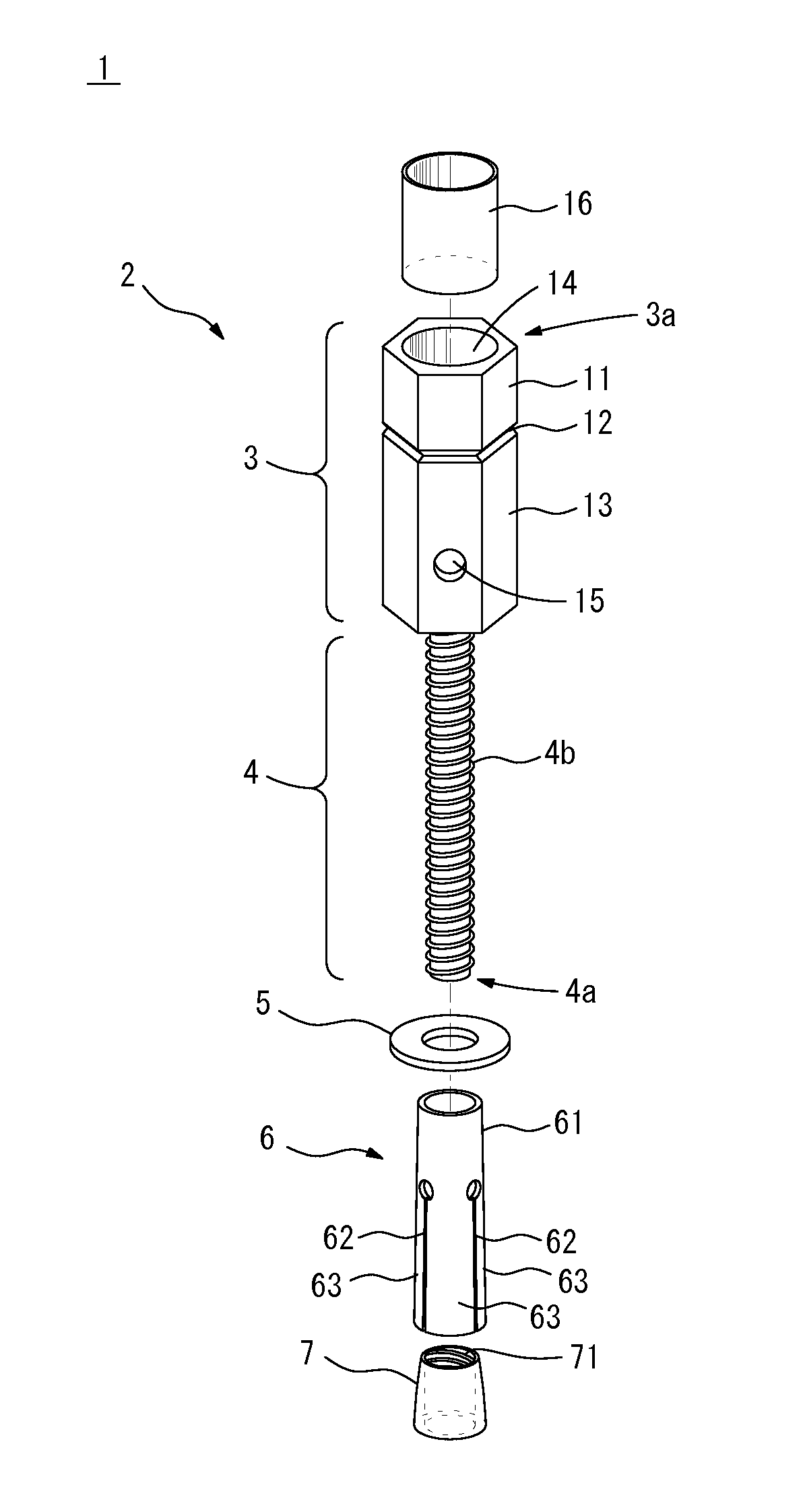
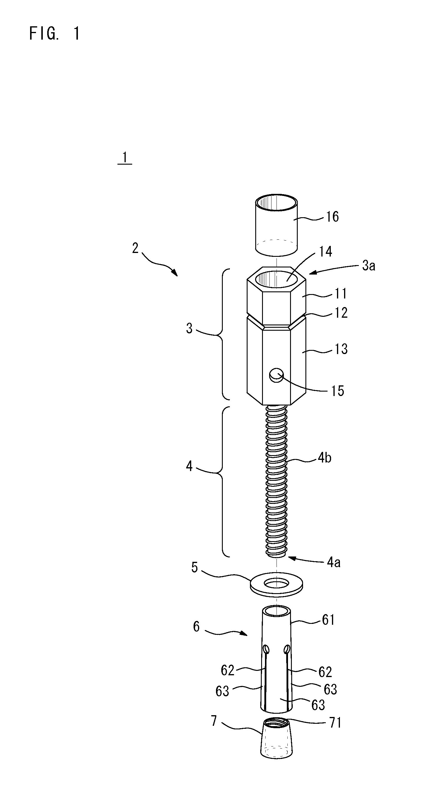
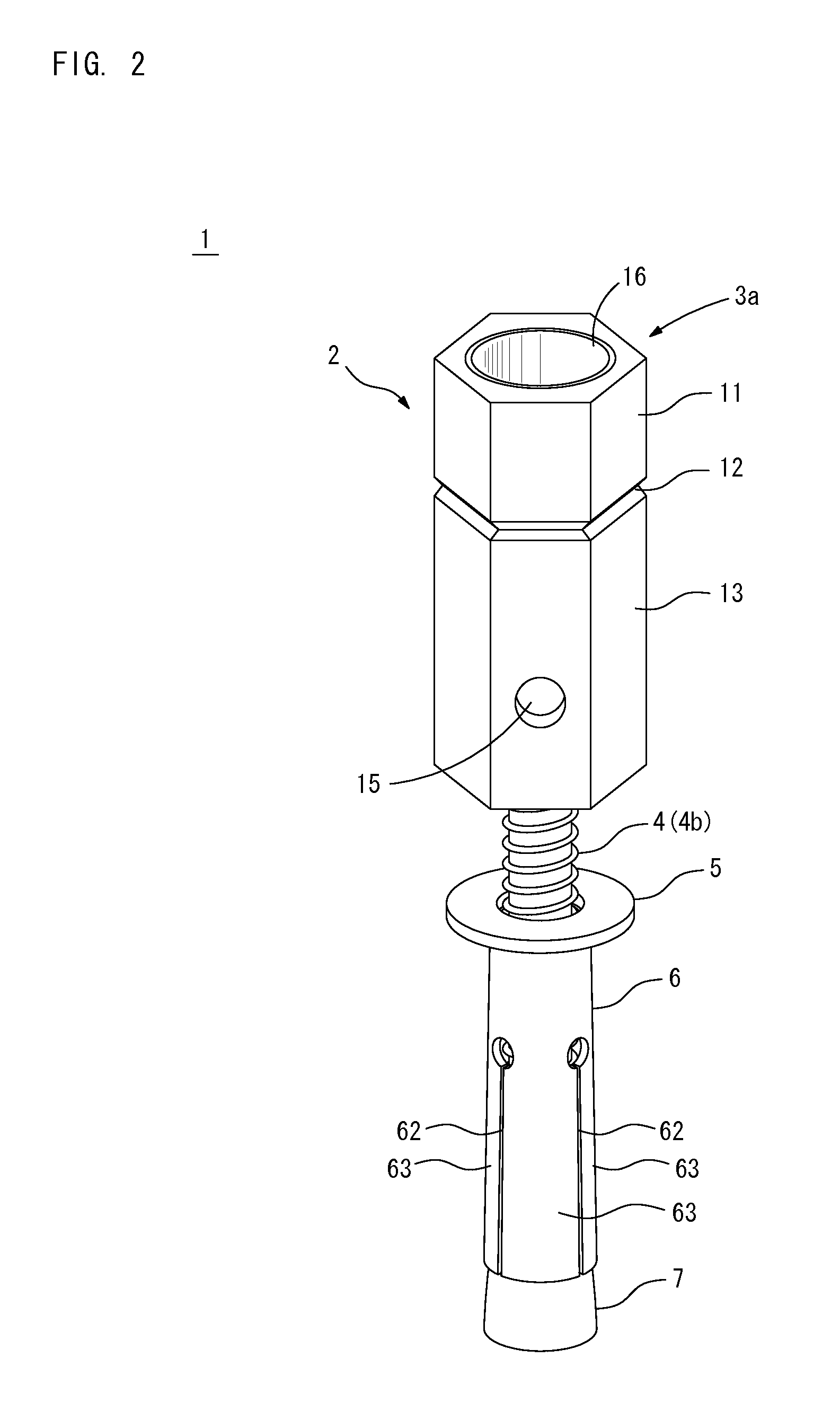
[0064]FIG. 1 is a perspective view of an anchor 1 of a first preferred embodiment of the present invention with all parts of the anchor 1 separated. FIG. 2 is a perspective view of the anchor 1 with all the parts of the anchor 1 assembled. FIG. 3 is a longitudinal sectional view of the anchor 1 with all the parts of the anchor 1 assembled.

[0065]The anchor 1 of the first preferred embodiment includes an anchor bolt 2, a washer 5, a spreading sleeve 6, a cone nut 7 and a cap member 16 as illustrated in FIG. 1. The anchor 1 is to be attached and fixed to various types of skeletons such as concrete buildings and structures, and is also suited for attachment to any of ceiling structures or surfaces of walls or floors.

[0066]The anchor bolt 2 includes a shaft part 4 of a predetermined length with a male screw thread 4b and a head part 3 connected to one end of the shaft part 4. The head part 3 and the shaft part 4 are, for example, formed integrally, and have the same axial center. The out...

second preferred embodiment

[0104]A second preferred embodiment of the present invention is described next. The tool is attached to the outer side surface of the tool attachment section 11 according to the first preferred embodiment as described above. In the second preferred embodiment, the tool is attached to the inner side surface of the tool attachment section 11. In the description given below, those elements which have already been described in the first preferred embodiment are represented by the same reference numerals, and these elements are not discussed repeatedly for the same description.

[0105]FIG. 15 is a perspective view of an anchor 1a of the second preferred embodiment with all the parts of the anchor 1a assembled. FIG. 16 is a longitudinal sectional view of the anchor 1a with all the parts of the anchor 1a assembled. The anchor 1a of the second preferred embodiment differs from the anchor 1 of the first preferred embodiment in that the head part 3 of the anchor bolt 2 has a different structure...

third preferred embodiment

[0112]A third preferred embodiment of the present invention is described next. The anchor bolt 2 is used as a part of the anchor 1 or the anchor 1a in the above-described first and second preferred embodiments. In the third preferred embodiment, a connecting nut 8 is used. In the description given below, those elements which have already been described in the first preferred embodiment are represented by the same reference numerals, and these elements are not discussed repeatedly for the same description.

[0113]FIG. 18 is a perspective view of an anchor 1b of the third preferred embodiment. FIG. 19 is a longitudinal sectional view of the anchor 1b with all the parts of the anchor assembled. As shown in FIG. 18, the anchor 1b of the third preferred embodiment includes the connecting nut 8, a shaft member 9, the washer 5, the spreading sleeve 6, the cone nut 7 and the cap member 16.

[0114]The shaft member 9 of a predetermined length in the axial direction has the outer side surface of a...


PUM


Abstract

An anchor bolt comprising: a shaft part with a male screw thread; and a head part connected to the shaft part and having an attachment hole with a closed-end bottom to receive a bolt therein defined at a tip surface of the head part and a breaking groove provided at an outer side surface of the head part. The breaking groove is formed at an outer surface of a portion in which the attachment hole is defined. A torque equal to or greater than a fixed value exerted on a tip portion between the tip surface and the breaking groove of the head part causes the breaking groove to be broken, thereby causing the tip portion between the tip surface and the breaking groove of the head part to be removed.

Description

[0001]This application is based on the applications No. 2011-022260 and No. 2011-132042 filed in Japan, the contents of which are hereby incorporated by reference.BACKGROUND OF THE INVENTION[0002]1. Field of the Invention[0003]The present invention relates to an anchor bolt, a connecting nut, a clamping nut and an anchor to be attached to various types of skeletons such as concrete buildings and structures.[0004]2. Background Art[0005]In order to attach hanging objects such as air conditioners, lighting fixtures, and various types of pipes to an existing ceiling structure of a building such as that made of concrete, anchors intended to support the hanging objects are fixed to the ceiling structure. The anchors are fixed to not only the ceiling structure but also surfaces such as that of a wall or a floor. Conventionally known anchors used for this purpose are disclosed for example in Japanese Patent Application Laid-Open No. 10-231583 (1998) (patent literature 1), and in Japanese Pa...

Claims


Application Information

Patent Timeline
Patent Type & Authority Patents(United States)
IPC IPC(8): F16B31/00F16B13/06F16B31/02
CPCF16B31/021F16B13/066
Inventor IKUNO, MAKOTO
Owner ENUPATTO
Why Eureka
Try Eureka