Mattress and side rail assembly with high airflow

a mattress and side rail technology, applied in the field of foam mattress assemblies, can solve the problems of preventing proper ventilation, affecting the comfort of users, and slow process of returning to the original shape, and achieve the effect of increasing airflow

Active Publication Date: 2015-03-24
DREAMWELL
View PDF34 Cites 22 Cited by
  • Summary
  • Abstract
  • Description
  • Claims
  • Application Information

AI Technical Summary

Problems solved by technology

One of the ongoing problems associated with foam mattress assemblies is user comfort.
However, the return to the original shape is a relatively slow process because of the viscoelastic cellular structure of these types of foams.
Unfortunately, the high density of foams used in current mattress assemblies, particularly those employing memory foam layers, generally prevents proper ventilation.
As a result, the foam material can exhibit an uncomfortable level of heat to the user after a period of time.
Additionally, these foams can retain a high level of moisture, further causing discomfort to the user and potentially leading to foul odors.
However, because substantially all of the cellular walls have been removed leaving behind a skeletal structure, these foams are inherently weak, provide less load-bearing capabilities relative to other non-reticulated viscoelastic foams, and are subject to fatigue at a rate faster than partially or completely closed cell foam structures.
Moreover, reticulated viscoelastic foams require special processing to remove the cellular walls to form the skeletal structure making these foams relatively expensive.
This can further reduce the ventilation of the mattress assembly and increase the amount of heat and / or moisture retained in the mattress.
These side rail assemblies can redirect the flow of air (and heat and moisture) back through the top sleeping surface, thereby adding to the discomfort experienced by the user.

Method used


Image

  • Mattress and side rail assembly with high airflow
  • Mattress and side rail assembly with high airflow

Examples


Embodiment Construction

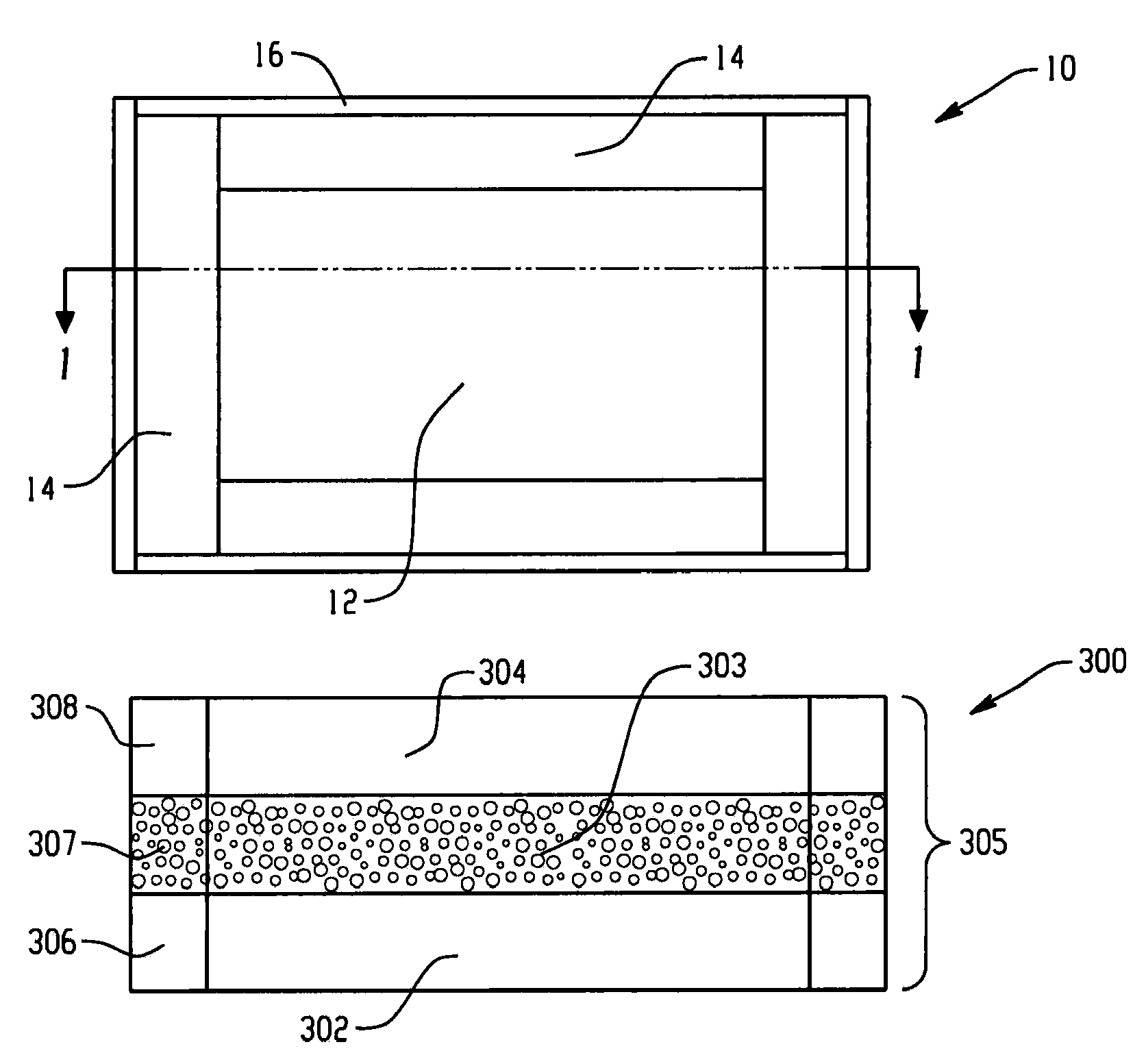
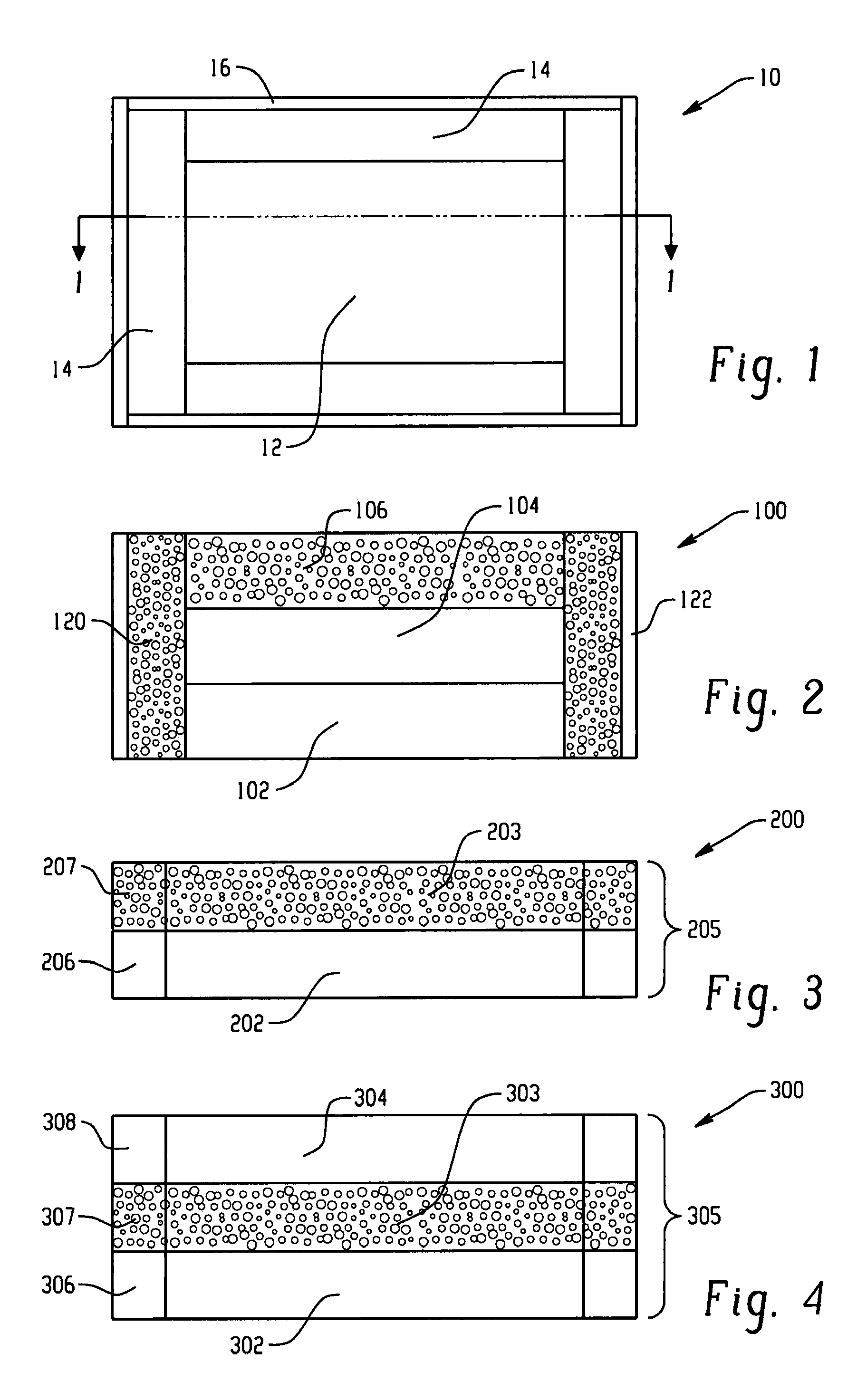
[0018]Disclosed herein are side rail assemblies (and mattress assemblies including the side rails), which provide user comfort with improved airflow to effectively dissipate user heat during use. The side rail assemblies advantageously include a high air flow foam that permits the flow of air and moisture from an inner core of the mattress assembly through the high air flow foam of the side rail assembly and out to the surrounding environment. Such removal of warm air and moisture can improve the sleeping experience of the mattress user.

[0019]The side rail assemblies can be disposed about a perimeter of the mattress inner core and provide support to the edge of a mattress. At least a portion of the side rail assembly, in some embodiments the entire assembly, in other embodiments one or more layers, is comprises of the high airflow foam, which is described in detail below.

[0020]Turning now to FIG. 1, a top down view representative of the various mattress assemblies is illustrated, wh...


PUM


Abstract

A side rail assembly for supporting an edge of a mattress includes a layer of a polyurethane foam comprising an open cellular structure, wherein the open cellular structure comprises about 10 to about 40 cells per inch, a hardness of about 35 pounds-force to about 100 pounds-force, and a density of about 1.2 pounds per cubic foot to about 2.0 pounds per cubic foot, wherein the layer is configured to be disposed about a perimeter of an inner core of the mattress and is configured to permit the flow of fluid from and to the inner core through the layer.

Description

CROSS-REFERENCE TO RELATED APPLICATIONS[0001]This application claims the benefit of U.S. Provisional Application Ser. No. 61 / 513,090 filed Jul. 29, 2011 and U.S. Provisional Application Ser. No. 61 / 513,091 filed Jul. 29, 2011, which are incorporated herein by reference in their entirety.BACKGROUND[0002]The present disclosure generally relates to foam mattress assemblies; specifically side rail assemblies of the mattress that exhibit increased airflow.[0003]Foam mattresses such as those formed of polyurethane foam, latex foam, and the like, are generally known in the art. One of the ongoing problems associated with foam mattress assemblies is user comfort. To address user comfort, these mattresses are often fabricated with multiple foam layers having varying properties such as density and hardness, among others, to suit the needs of the intended user. More recently, manufacturers have employed so called memory foam, also commonly referred to as viscoelastic foams, which are generally...

Claims


Application Information

Patent Timeline
Patent Type & Authority Patents(United States)
IPC IPC(8): A47C17/00A47C27/14
CPCA47C27/14
Inventor CHUNGLO, CHRISTOPHER F.
Owner DREAMWELL
Why Eureka
Try Eureka