Lamp guard

a technology for lamp cages and lamps, applied in fixed installations, lighting and heating devices, lighting support devices, etc., can solve the problems of special vulnerability of light in construction sites to damage and destruction, and achieve the effect of reducing material waste and needless energy consumption

Active Publication Date: 2015-03-24
SCHALCH III LOUIS G
View PDF3 Cites 1 Cited by
  • Summary
  • Abstract
  • Description
  • Claims
  • Application Information

AI Technical Summary

Benefits of technology

[0019]Another, though not final, object of the present invention is to provide a light cage that may be reused an indefinite number of times, so as to minimize material waste and the needless consumption of energy for and manufacturing and disposal.

Problems solved by technology

Lights in construction sites are especially vulnerable to damage and destruction.

Method used


Image

  • Lamp guard
  • Lamp guard
  • Lamp guard

Examples


Embodiment Construction

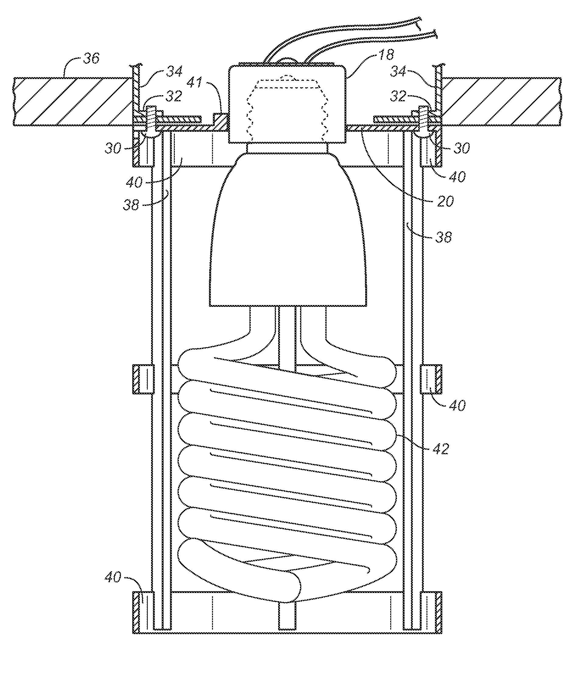
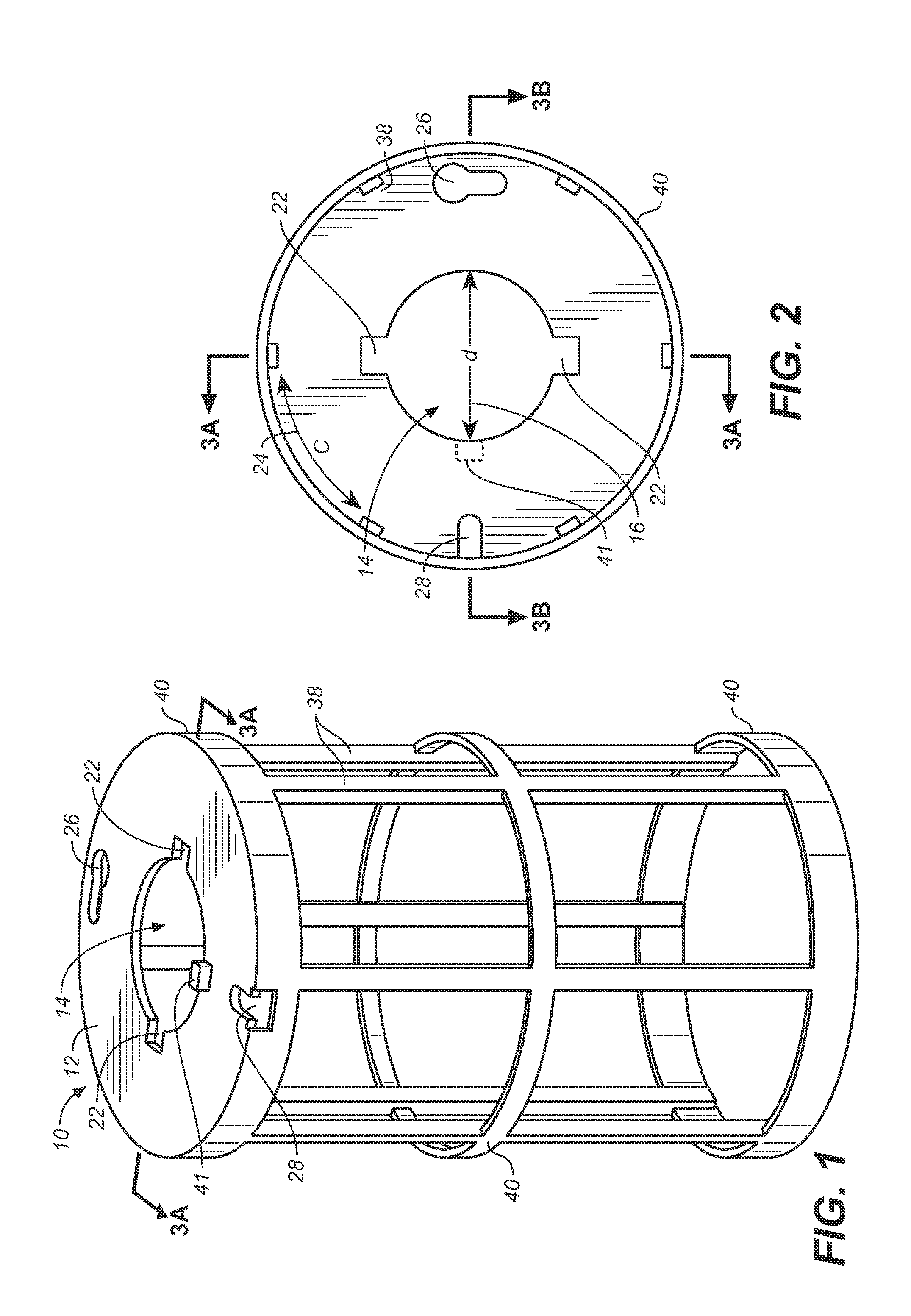
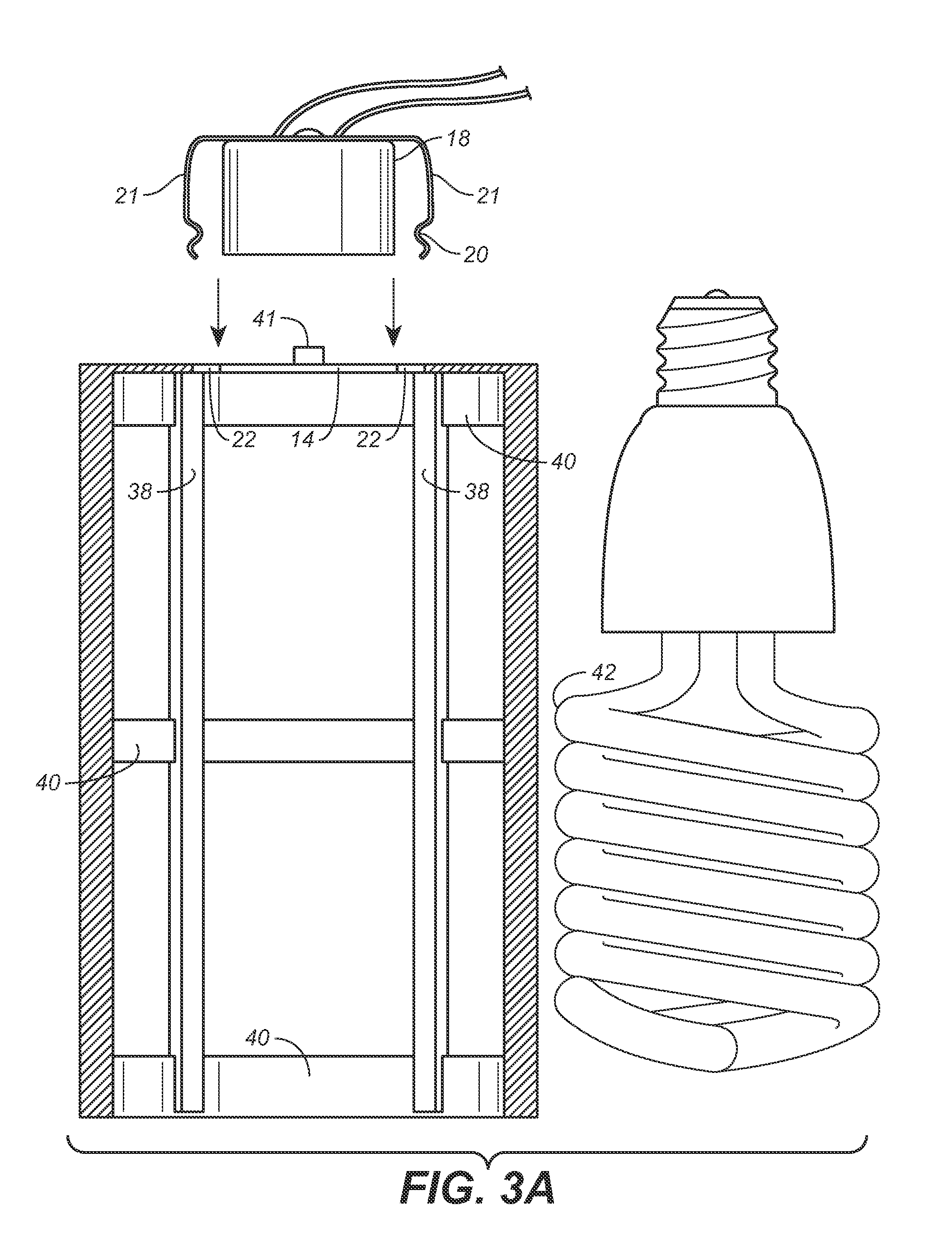
[0025]Referring to FIGS. 1 through 3B, wherein like reference numerals refer to like components in the various views, there is illustrated therein a new and improved lamp guard, generally denominated 10 herein. FIGS. 1-3B illustrate a preferred embodiment of the lamp guard. Collectively, these views show that the inventive apparatus comprises a planar base plate 12 having a center hole 14 with a diameter 16 sized for a light socket 18, preferably a medium base light socket. As is shown in FIG. 3A, the light socket may be used in connection with a front mount snap-in type socket with shoulder springs, such that the base plate is snapped onto shoulder spring—the annular groove 20 of the shoulder spring accepts and is captured by the base plate center hole, such that the arms 21 of the shoulder spring on the socket fit within opposing side slots 22 disposed 180 degrees apart from one another and extending radially from the center hole, such that the shoulder spring arms are securely ur...


PUM


Abstract

A light guard that includes a planar base plate having a center hole sized to permit the passage of a light socket and opposing side slots disposed substantially 180 degrees apart from one another, the base plate having an outer circumference sized substantially the same as the outer dimension of a selected electrical outlet box. The base plate also includes a keyhole slot proximate said outer circumference of the base plate and a transverse slot proximate the outer circumference of the base plate, each of the slots sized to accommodate screws for securing and mounting the base plate onto an outlet box or a plaster ring mounted on the outlet box. Spokes of substantially equal length extend from the base plate, and at least two rings connect the spokes to form a light bulb cage with an open bottom end, thereby providing free access to an installed light bulb.

Description

CROSS REFERENCES TO RELATED APPLICATIONS[0001]The present application claims the benefit of U.S. Provisional Patent Application Ser. No. 61 / 351,564 filed Jun. 4, 2010 (Jun. 4, 2010.)SEQUENCE LISTING[0002]Not applicable.STATEMENT REGARDING FEDERALLY SPONSORED RESEARCH OR DEVELOPMENT[0003]Not applicable.THE NAMES OR PARTIES TO A JOINT RESEARCH AGREEMENT[0004]Not applicable.INCORPORATION-BY-REFERENCE OF MATERIAL SUBMITTED ON A COMPACT DISC[0005]Not applicable.BACKGROUND OF THE INVENTION[0006]1. Field of the Invention[0007]The present invention relates generally to lamp guards, and more particularly to a lamp cage or lamp guard for protecting an electric light or lamp screwed into an electric socket installed in an outlet box. The inventive apparatus is particularly well-suited for use in mounting the cage on outlet boxes newly installed in a wall or ceiling in a building under construction.[0008]2. Discussion of Related Art Including Information Disclosed Under 37 CFR §§1.97, 1.98[0009...

Claims


Application Information

Patent Timeline
Patent Type & Authority Patents(United States)
IPC IPC(8): F21V15/00
CPCF21V15/02F21V17/06
Inventor SCHALCH, III, LOUIS G.
Owner SCHALCH III LOUIS G
Why Eureka
Try Eureka