Process and apparatus for organic vapor jet deposition

Active Publication Date: 2008-09-25
THE TRUSTEES FOR PRINCETON UNIV
View PDF13 Cites 527 Cited by
  • Summary
  • Abstract
  • Description
  • Claims
  • Application Information

AI Technical Summary

Benefits of technology

[0015]An embodiment of the present invention further provides that under the appropriate conditions of substrate temperature, reactor pressure, and nozzle geometry, an array of sharp-edged pixels with a resolution of about 1 μm is achievable with jet deposition if the nozzle-substrate separation, s, is within the molecular mean free path of the carrier gas, A. In addition, because of the unidirectional flow, use of a heavier carrier gas can provide better directionality of deposition and subsequently sharper pixels.
[0016]One advantage of certain embodiments of the present invention is that material waste is minimized due to the heating of the nozzle and the directional flow. For example, the nozzle may be heated to a temperature sufficient to avoid physisorbtion (condensation) of organic material on nozzle surfaces, thereby reducing waste, and also reducing the need to clean the nozzle. The substrate may be cooled to enhance deposition characteristics, and avoid a situation where the carrier gas heats the substrate to the point that organic material will not deposit. Another advantage is the absence of the masking step, resulting in an increased rate of production, a more compact deposition apparatus design, and the elimination of contamination from a shadow mask. In high-resolution deposition requiring a separation distance s typically less than 1 mm,

Problems solved by technology

However, control of film thickness uniformity and dopant concentrations over large areas needed for manufactured products can be difficult when using vacuum evaporation (see S. Wolf and R. N. Tauber, Silicon Processing for the VLSI Era (Lattice, 1986)).
In addition, a considerable fraction of the evaporant coats the cold walls of the deposition chamber.
Over time, inefficient use of materials results in a thick coating which can flake off, leading to particulate contamination of the system and substrate.
The potential throughput for vacuum evaporated organic thin film devices is low, resulting in high production costs

Method used


Image

  • Process and apparatus for organic vapor jet deposition
  • Process and apparatus for organic vapor jet deposition
  • Process and apparatus for organic vapor jet deposition

Examples


Example

[0039]Embodiments of the present invention are directed to a process of patterned deposition of organic materials onto substrates utilizing the vapor transport mechanisms of organic vapor phase deposition, and to an apparatus for performing this process of patterned deposition. In one embodiment, the process comprises: transporting organic vapors via an inert carrier gas moving at a flowrate V from a source cell, through a timed valve, and into a nozzle block, wherein the transport occurs at low pressure P; ejecting the organic vapors from the nozzle block onto a cooled substrate via the inert carrier gas moving at a flowrate V; and laterally translating the cooled substrate, which is maintained at a distance s from the ejection end of the nozzle block, at a rate v. The rate of translation is synchronized with the timed valve to create the desired patterned deposition of organic materials.

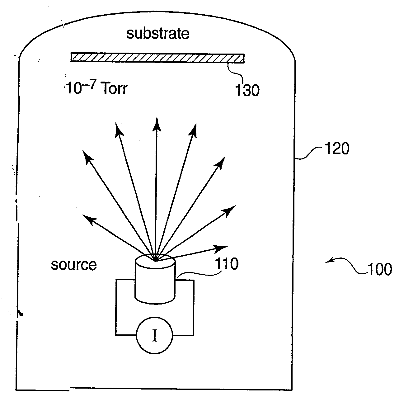
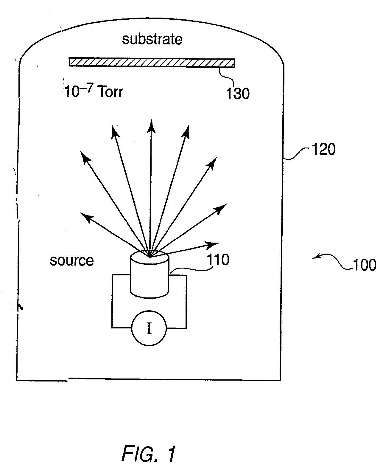
[0040]FIG. 1 shows a vacuum thermal evaporation (VTE) system 100. A source 110 is heated such t...


PUM

PropertyMeasurementUnit
Lengthaaaaaaaaaa
Lengthaaaaaaaaaa
Lengthaaaaaaaaaa

Abstract

A method of fabricating an organic film is provided. A non-reactive carrier gas is used to transport an organic vapor. The organic vapor is ejected through a nozzle block onto a cooled substrate, to form a patterned organic film. A device for carrying out the method is also provided. The device includes a source of organic vapors, a source of carrier gas and a vacuum chamber. A heated nozzle block attached to the source of organic vapors and the source of carrier gas has at least one nozzle adapted to eject carrier gas and organic vapors onto a cooled substrate disposed within the vacuum chamber.

Description

CROSS-REFERENCE TO RELATED APPLICATIONS[0001]This patent application claims priority benefits to the following U.S. patent applications: 60,317,215 (filed Sep. 4, 2601), 60 / 316,264 (filed on Sep. 4, 2001), 60 / 316,968 (filed on Sep. 5, 2001), and 60 / 332,090 (filed Nov. 21, 2001). These patent applications are incorporated by reference in their entireties. This patent application is related to simultaneously filed patent application Ser. No. ______, attorney docket no. 10020 / 21904, which is incorporated by reference in its entirety.STATEMENT REGARDING GOVERNMENT RIGHTS[0002]This invention was made with Government support under Contract No. F49620-92-J-05 24 (Princeton University), awarded by the U.S. Air Force OSR (Office of Scientific Research). The Government has certain rights in this invention.FIELD OF THE INVENTION[0003]The present invention is directed to a process of patterned deposition of organic materials onto substrates which utilizes the vapor transport mechanisms of organ...

Claims


Application Information

Patent Timeline
IPC IPC(8): C23C16/00
CPCC23C14/24C23C14/12
Inventor SHTEIN, MAXFORREST, STEPHEN R.
Owner THE TRUSTEES FOR PRINCETON UNIV
Why Eureka
Try Eureka