Road edge identification method and a road edge identification system

A road edge and identification method technology, applied in the field of smart cars, can solve the problems of road edge results, such as the effect of light on the environment, and achieve the effect of improving efficiency and reducing the amount of calculation.

Active Publication Date: 2019-03-26
FAW VOLKSWAGEN AUTOMOTIVE CO LTD
View PDF6 Cites 13 Cited by
  • Summary
  • Abstract
  • Description
  • Claims
  • Application Information

AI Technical Summary

Problems solved by technology

[0004] The purpose of the present invention is to provide a road edge recognition method and system, which solves the problem in the prior art that road images are collected through a camera, and the obtained road edge results are greatly affected by the light environment

Method used


Image

  • Road edge identification method and a road edge identification system
  • Road edge identification method and a road edge identification system
  • Road edge identification method and a road edge identification system

Examples


Embodiment 1

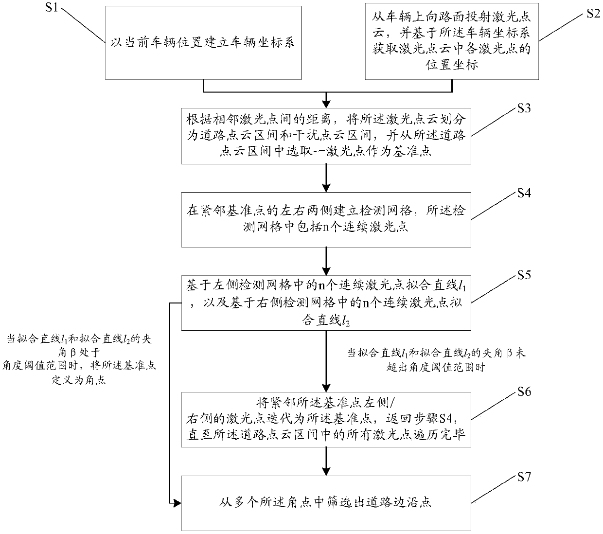
[0068] see Figure 1-6 , this embodiment provides a road edge recognition method, including:

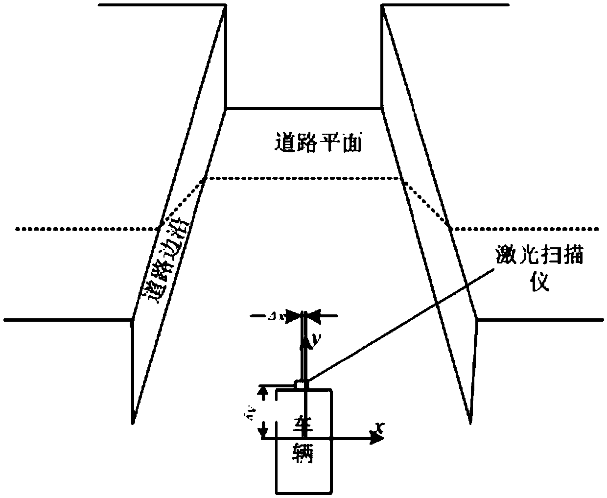
[0069] Step S1, establishing a vehicle coordinate system based on the current vehicle position;

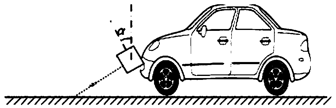
[0070] Step S2, projecting a laser point cloud from the vehicle to the road surface, and obtaining the position coordinates of each laser point in the laser point cloud based on the vehicle coordinate system;

[0071] Step S3, according to the distance between adjacent laser points, divide the laser point cloud into a road point cloud interval and an interference point cloud interval, and select a laser point from the road point cloud interval as a reference point;

[0072] Step S4, establishing a detection grid on the left and right sides adjacent to the reference point, and the detection grid includes n consecutive laser points;

[0073] Step S5, fitting a straight line l based on n consecutive laser points in the detection grid on the left 1 , and a straight line l based on n conse...

Embodiment 2

[0096] see figure 1 and Figure 7 , this embodiment provides a road edge recognition system, including a coordinate system establishment unit 1, a laser scanning device 2, a coordinate conversion unit 3, an interval division unit 4, a detection grid unit 5, a corner point judgment unit 6, and a reference point iteration unit 7 and screening output unit 8;

[0097] The coordinate system establishment unit 1 is used to establish a vehicle coordinate system with the current vehicle position;

[0098] The laser scanning device 2 is used to project a laser point cloud from the vehicle to the road surface;

[0099] The coordinate conversion unit 3 is used to obtain the position coordinates of each laser point in the laser point cloud based on the vehicle coordinate system;

[0100] The interval division unit 4 is used to divide the laser point cloud into a road point cloud interval and an interference point cloud interval according to the distance between adjacent laser points, a...


PUM


Abstract

The invention discloses a road edge identification method and a road edge identification system, which solve the problem that the road edge result obtained by collecting road images through a camera in the prior art is greatly influenced by a light environment. The method comprises the following steps: step S1, establishing a vehicle coordinate system according to the current vehicle position; step 2, projecting laser point cloud on that road surface from the vehicle, and obtaining the position coordinates of each laser point in the laser point cloud based on the vehicle coordinate system; Step S3, according to the distance between adjacent laser points, dividing the laser point cloud into a road point cloud section and an interference point cloud section, and selecting a laser point as areference point from the road point cloud section; Step S4, establishing a detection mesh on the left and right sides adjacent to the reference point, and n continuous laser points are included in thedetection mesh. The system comprises the method proposed in the technical proposal.

Description

technical field [0001] The invention relates to the technical field of smart cars, in particular to a road edge recognition method and system. Background technique [0002] Autonomous driving (including assisted driving) is an important direction for the development of smart cars, and more and more vehicles have begun to apply automatic driving systems to realize the automatic driving function of vehicles. Generally, the automatic driving system may need to determine the drivable area of ​​the vehicle at any time. In the process of determining the drivable area, an important aspect is to determine the road edge of the current driving road. [0003] The existing more commonly used road edge recognition method is to use the camera to collect road images, and after the image recognition system extracts and analyzes the position coordinates of the road edge in the image, but in the actual application process, the image taken by the lens is affected by the light environment facto...

Claims


Application Information

Patent Timeline
Patent Type & Authority Applications(China)
IPC IPC(8): G06K9/00G01B11/00G01B11/03G01B11/06
CPCG01B11/002G01B11/03G01B11/0608G06V20/588
Inventor 肖强赵瑜东陈双双
Owner FAW VOLKSWAGEN AUTOMOTIVE CO LTD
Why Eureka
Try Eureka