Machine for inflating and sealing an inflatable structure

a technology for inflatable structures and machines, applied in the field of inflatable structures, can solve the problems of excessive noise, large size of early machines for forming inflatable cushions, and high pressure, and achieve the effect of efficient and quiet inflating inflatable structures

Active Publication Date: 2015-03-31
SEALED AIR U S
View PDF17 Cites 24 Cited by
  • Summary
  • Abstract
  • Description
  • Claims
  • Application Information

AI Technical Summary

Benefits of technology

[0008]These and other advantages are provided by the herein presented machines for inflating an inflatable structure having a longitudinal edge, at least two sheets, and a series of inflatable chambers formed between the sheets, each of the inflatable chambers being capable of holding therein a quantity of a fluid and having an opening proximate the longitudinal edge for receiving the fluid during inflation. Such machines and associated methods may efficiently and quietly inflate inflatable structures.
[0009]In particular, the machines may include a drive for advancing the inflatable structure in a machine direction substantially parallel to the longitudinal edge, an inflation nozzle positioned to direct the fluid into the openings of the inflatable chambers as the inflatable structure is advanced in the machine direction to thereby inflate the inflatable chambers, a sealing device located proximate the inflation nozzle for sealing closed the openings of the inflatable chambers after they are inflated with the fluid, and a sheet engagement device configured to engage the sheets together along the longitudinal edge of the inflatable structure and adjacent to the inflation nozzle to facilitate inflation of the inflatable chambers prior to the inflatable chambers being sealed. The sheet engagement device may both aid in directing fluid into the inflatable chambers by preventing it from flowing out the longitudinal edge, and may further help keep the openings to the inflatable chambers open during inflation by contracting the length of the longitudinal edge.
[0011]In a further embodiment, the sheet engagement device may comprise one or more engagement rollers. The engagement rollers may in turn comprise a first plurality of rollers positioned on one side of the sheets and a second plurality of rollers positioned on an opposite side of the sheets. One or more engagement rollers may comprise teeth, and the first plurality of rollers may intermesh with the second plurality of rollers so as to thereby reduce a dimension of the longitudinal edge in the machine direction.
[0012]The machine may further include an engaging assembly and an opposing assembly with the drive advancing the inflatable structure therebetween. A release mechanism may be configured to displace at least a portion of the opposing assembly from the engaging assembly by a displacement distance and may also displace the inflation nozzle from the engaging assembly by an intermediate displacement distance which is less than the displacement distance of the engaging and opposing assemblies. Such displacements may make feeding an inflatable structure into the machine easier.

Problems solved by technology

Earlier machines for forming inflated cushions tended to be rather large, expensive and complex.
Many such machines, however, produce excessive noise and require relatively high pressures for the fluid used to inflate the inflatable structures.

Method used


Image

  • Machine for inflating and sealing an inflatable structure
  • Machine for inflating and sealing an inflatable structure
  • Machine for inflating and sealing an inflatable structure

Examples


Embodiment Construction

[0024]The present invention now will be described more fully hereinafter with reference to the accompanying drawings, in which some, but not all embodiments of the invention are shown. Indeed, this invention may be embodied in many different forms and should not be construed as limited to the embodiments set forth herein; rather, these embodiments are provided so that this disclosure will satisfy applicable legal requirements. Like numbers refer to like elements throughout.

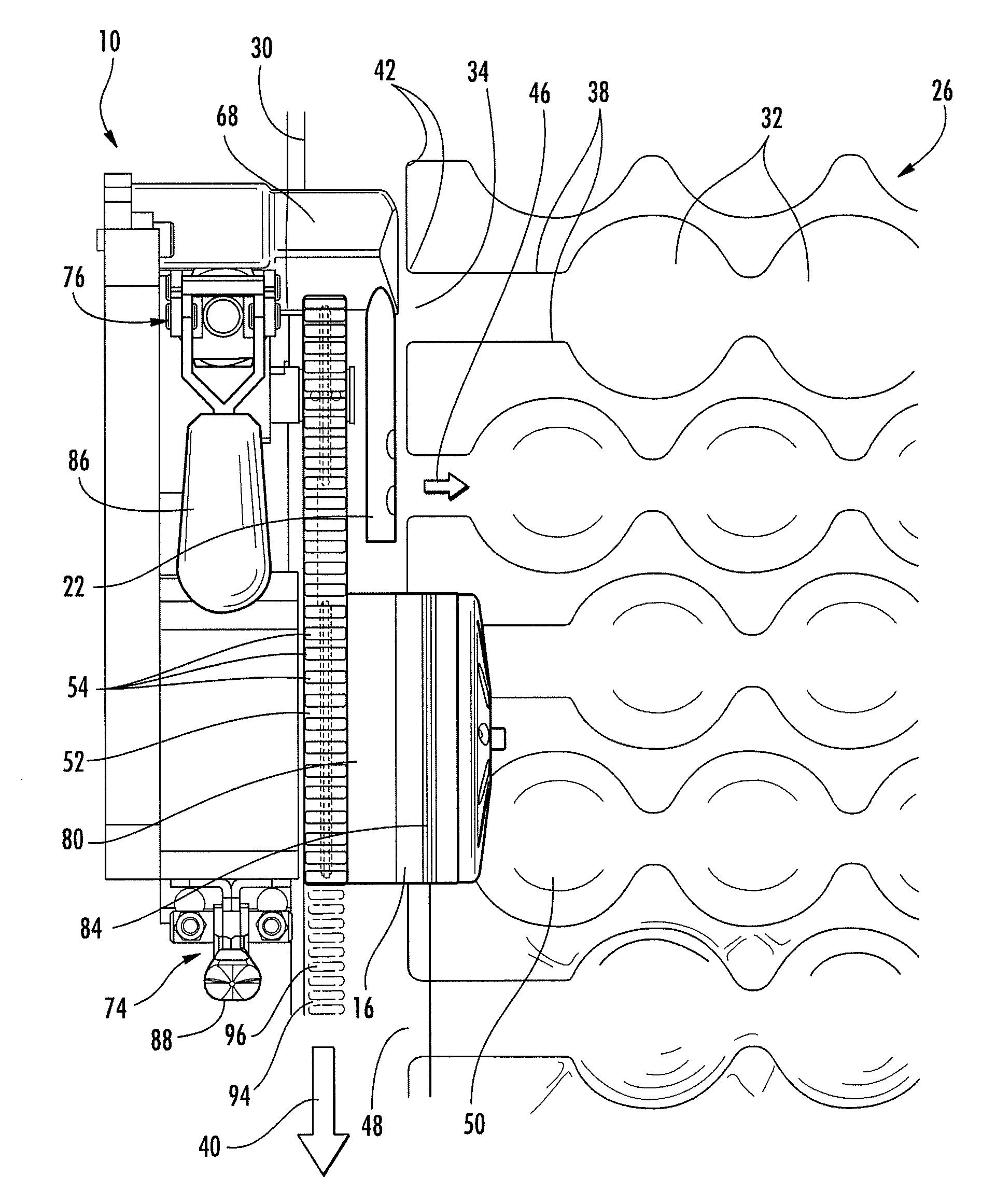
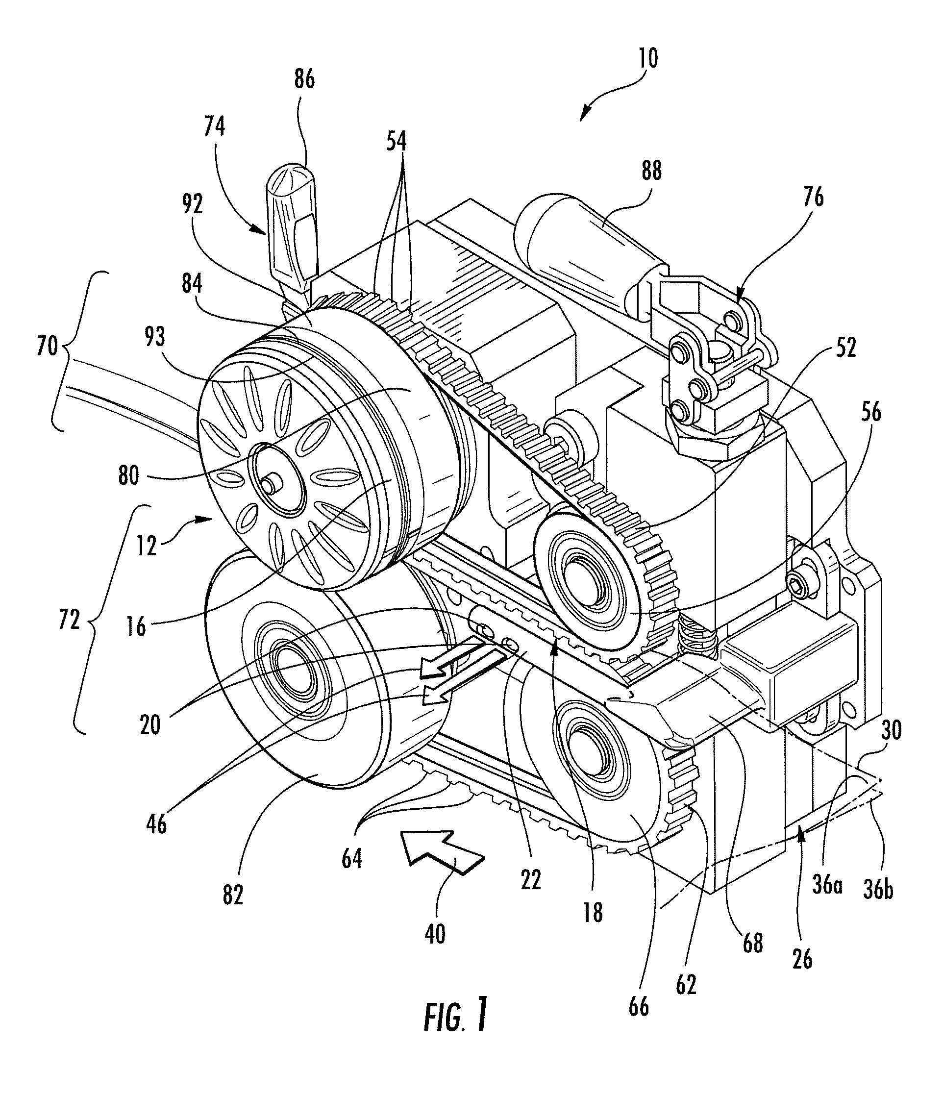
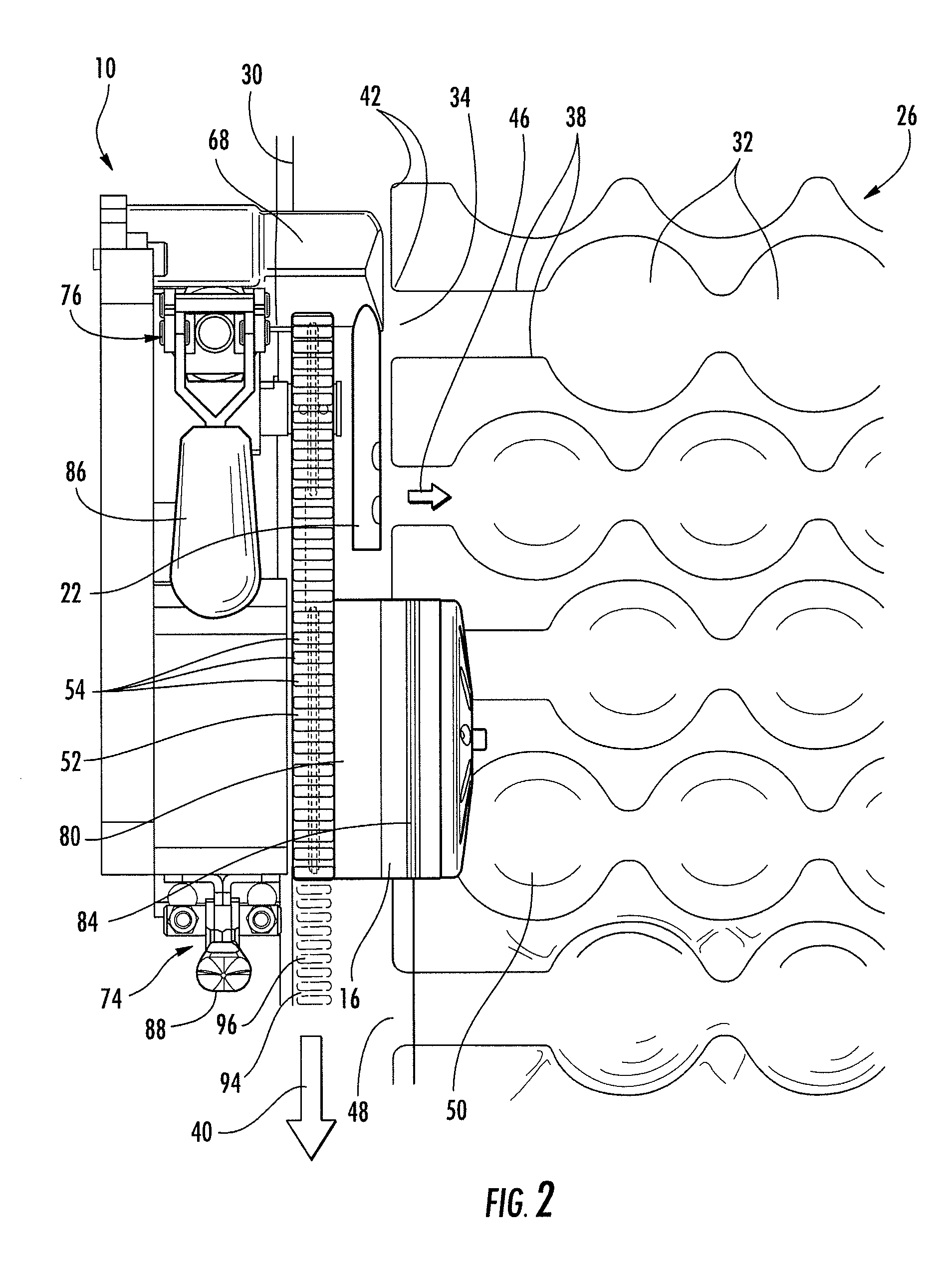
[0025]FIG. 1 illustrates a machine 10 for inflating and sealing an inflatable structure 26 in accordance with the present invention. Machine 10 generally comprises a drive 12, an inflation nozzle 22, a sealing device 16, and a sheet engagement device 18. The drive 12 may comprise a drive roller 80 and a backing roller 82 which may be positioned such that a nip, i.e., an area of tangential contact, is formed therebetween when the drive roller and the backing roller contact. At least one of the rollers, such as the ...


PUM

PropertyMeasurementUnit
dimensionaaaaaaaaaa
speedaaaaaaaaaa
displacement distanceaaaaaaaaaa

Abstract

A machine for inflating and sealing an inflatable structure having a longitudinal edge generally comprises a drive, an inflation nozzle, a sealing device, and a sheet engagement device. The machine may define an engaging assembly and an opposing assembly. The drive may be rotationally coupled to the sheet engagement device such that when the drive rotates, the engagement device also rotates. The sheet engagement device may comprise one or more engagement rollers which may have a plurality of teeth thereon. A first plurality of rollers and a second plurality of rollers comprising the engagement rollers may intermesh between a drive roller and a backing roller on the longitudinal edge of the inflatable structure. Thereby, the sheets of the inflatable structure may be engaged together and the length of the longitudinal edge may contract to facilitate inflation. The resulting inflated inflatable structure may comprise an embossed longitudinal edge.

Description

CROSS-REFERENCE TO RELATED APPLICATION[0001]This application is a continuation-in-part of U.S. application Ser. No. 12 / 419,133, filed Apr. 6, 2009, which is hereby incorporated herein in its entirety by reference.BACKGROUND OF THE INVENTION[0002]1. Field of the Invention[0003]The present invention generally relates to inflatable structures, such as inflatable packaging, and further to improved machines and methods for inflating the same.[0004]2. Description of Related Art[0005]Inflatable structures constitute an important part of the packaging industry. Inflatable structures are commonly used as cushions to package items, either by wrapping the items in the inflatable structures and placing the wrapped items in a shipping carton, or by simply placing one or more inflatable structures inside of a shipping carton along with an item to be shipped. The cushions protect the packaged item by absorbing impacts that might otherwise be fully transmitted to the packaged item during transit, a...

Claims


Application Information

Patent Timeline
Patent Type & Authority Patents(United States)
IPC IPC(8): B65B31/02B65B31/04B65B31/06B31D5/00
CPCB31D5/0073B65B31/06B65B31/02B65B31/04B31D2205/0047B31D2205/0064B65D81/052
Inventor SPERRY, LAURENCEMURCH, BRIAN A.
Owner SEALED AIR U S
Why Eureka
Try Eureka