Curtain airbag device

a curtain and airbag technology, applied in the direction of pedestrian/occupant safety arrangement, vehicular safety arrangment, vehicle components, etc., can solve the problems of affecting the proper operation of the curtain, the limit of the window area that could be covered properly, and the loose cloth portion

Inactive Publication Date: 2008-12-09
MAZDA MOTOR CORP
View PDF14 Cites 6 Cited by
  • Summary
  • Abstract
  • Description
  • Claims
  • Application Information

AI Technical Summary

Benefits of technology

[0012]The present invention has been devised in view of the above-described problems, and an object of the present invention is to provide a curtain airbag device that can maintain a proper tension of a curtain portion even if an airbag inflation force reduces and can provide a prompt inflation of the curtain portion when a fixed position is moved.

Problems solved by technology

This conventional way of generating the tension, however, would require a relatively large volume of the inflatable airbag portion to cover the large window portion properly and lots of gas to inflate the large inflatable airbag.
Thus, the window area that could be covered properly has a limit.
However, in the former device of the above-described patent publication, since the position of the curtain portion is limited by the cloth portion interconnecting the tension-providing support point and the curtain portion and thereby the fixed position of the curtain portion is not movable, the cloth portion becomes loose when the inflation force at the curtain reduces.
As a result, there is a problem that the proper tension would not be maintained at the curtain portion.
Meanwhile, although it may be considered that the fixed position of the curtain portion is movable like the latter device of the above-described patent publication, there is a problem that when the fixed position of the curtain portion is moved, the sliding resistance would occur between the guide rail and the curtain portion, so that the prompt inflation would not be attained.
Also, in the case where the guide rail is deformed at the vehicle crash, there is a concern that the proper inflation of the airbag would be provided.

Method used


Image

  • Curtain airbag device
  • Curtain airbag device
  • Curtain airbag device

Examples


embodiment 1

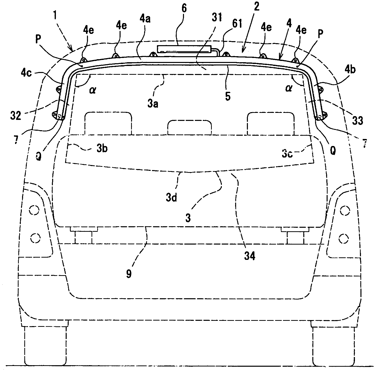
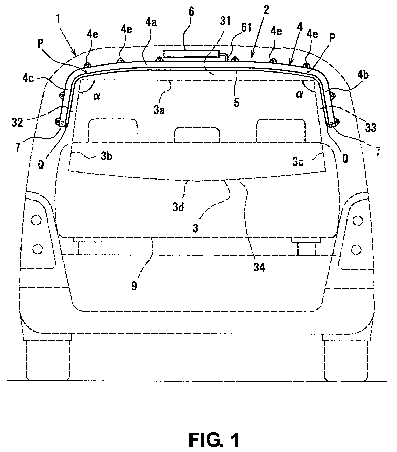
[0081]An embodiment 1 of the curtain airbag device of the present invention will be described referring to FIGS. 1-5. The embodiment 1 shows a curtain airbag device 2 that is provided at a back door 1 of the vehicle. FIG. 1 is a back view of the vehicle showing the curtain airbag device 2 in a folded state. FIG. 2 is a back view of the vehicle showing the curtain airbag device 2 in an inflated state. FIG. 3A is a detailed view of a major portion of a support pin of the curtain airbag device 2 in the folded state. FIG. 3B is a detailed view of the major portion of the support pin of the curtain airbag device 2 in the inflated state. FIG. 4 is a sectional view taken along line A-A of FIG. 3A. FIG. 5 is a perspective view showing a major side portion of a curtain portion.

[0082]The curtain airbag device 2, as shown in FIGS. 1 and 2, is placed at the peripheral portion of a back window 3 of the back door 1. The curtain airbag device 2 comprises a base casing 4 that is located along three...

embodiment 2

[0132]Next, the curtain airbag device according to another embodiment 2 will be described referring to FIG. 9. A curtain airbag device 102 is provided at the back door 1 as well as the device of the embodiment 1. Herein, the same components are denoted by the same characteristics as those described above, and descriptions of those are omitted here.

[0133]The curtain airbag device 102 of the present embodiment is configured such that although the vertical length of a curtain portion 105 is set to be short compared with the embodiment 1, the proper tension can be provided at the tension line T as well.

[0134]Namely, the curtain portion 105 is formed such that it does not cover the entire area of the back window 3 but its lower end 105a extends to a portion just below an upper end 91a of a seat back 91 of a rear seat 9 when it is inflated.

[0135]Thereby, the curtain portion 105 itself is made small, so the proper tension can be also provided even with a smaller gas volume.

[0136]Also, sinc...

embodiment 3

[0139]Next, the curtain airbag device according to another embodiment 3 will be described referring to FIG. 10. A curtain airbag device 202 is provided at the back door 1 as well as the device of the embodiments 1 and 2. Herein, the same components are denoted by the same characteristics as those described above, and descriptions of those are omitted here.

[0140]A curtain portion 205 of the curtain airbag device 202 has a lower inflatable portion 257 that extends in the vehicle width direction. Herein, the lower inflatable portion 257 is formed such that its both ends are hocked by both-side edges 32, 33 of the back window 3 when the airbag is inflated. Thereby, the tension can be further generated at the lower portion below the tension line T between the support pins 7, 7.

[0141]Accordingly, even when there occurs some force operative to move the lower portion of the curtain portion 205 below the support pins 7, 7 towards the outside the vehicle, the curtain portion 205 can be surely...


PUM


Abstract

When the airbag portion is inflated, the tip portions of the curtain portion are moved downward and thereby the tension portions connected by the bands are pulled down to the position of the support pins as shown in FIG. 6B. Thus, the tension can be provided to the curtain portion at a portion between the support pins with the length V between the right-side tension portion and the left-side tension portion, which is shorter than the three-side length (X+Y+Z).

Description

BACKGROUND OF THE INVENTION[0001]The present invention relates to a curtain airbag device, in particular to the curtain airbag device that is applicable to a vehicle, building, air craft, train, ship, space vehicle, space station etc., and that is operative to be inflated so as to promptly cover an opening portion such as a window or a door (hereinafter, referred to as a window portion).[0002]Conventionally, the curtain airbag device that is inflated in a curtain shape to cover the window portion promptly is known.[0003]This curtain airbag device is operative such that an airbag is placed in a folded state at a periphery of the window portion, and in a specified situation (for example, at the vehicle crash) the airbag is inflated so as to cover the window portion.[0004]Herein, it is generally necessary to provide a specified tension to the curtain-shaped inflated airbag in order to cover the window portion properly, so it has been important how such tension could be provided.[0005]I...

Claims


Application Information

Patent Timeline
Patent Type & Authority Patents(United States)
IPC IPC(8): B60R21/16B60R21/231B60R21/232B60R21/2338
CPCB60R21/232B60R21/2338B60R2021/23153B60R2021/23386
Inventor HIRATA, MOTOHARU
Owner MAZDA MOTOR CORP
Why Eureka
Try Eureka