Airbag and airbag device

a technology of airbags and airbags, which is applied in the direction of pedestrian/occupant safety arrangements, vehicular safety arrangments, vehicle components, etc., can solve the problems of insufficient thickness of the inflated airbag in the longitudinal direction of the vehicle body at the upper end side, and the occupant head and the occupant counter surface are at risk, so as to prevent and suppress the flopping of the lower portion

Active Publication Date: 2012-06-12
JOYSON SAFETY SYST JAPAN GK
View PDF12 Cites 6 Cited by
  • Summary
  • Abstract
  • Description
  • Claims
  • Application Information

AI Technical Summary

Benefits of technology

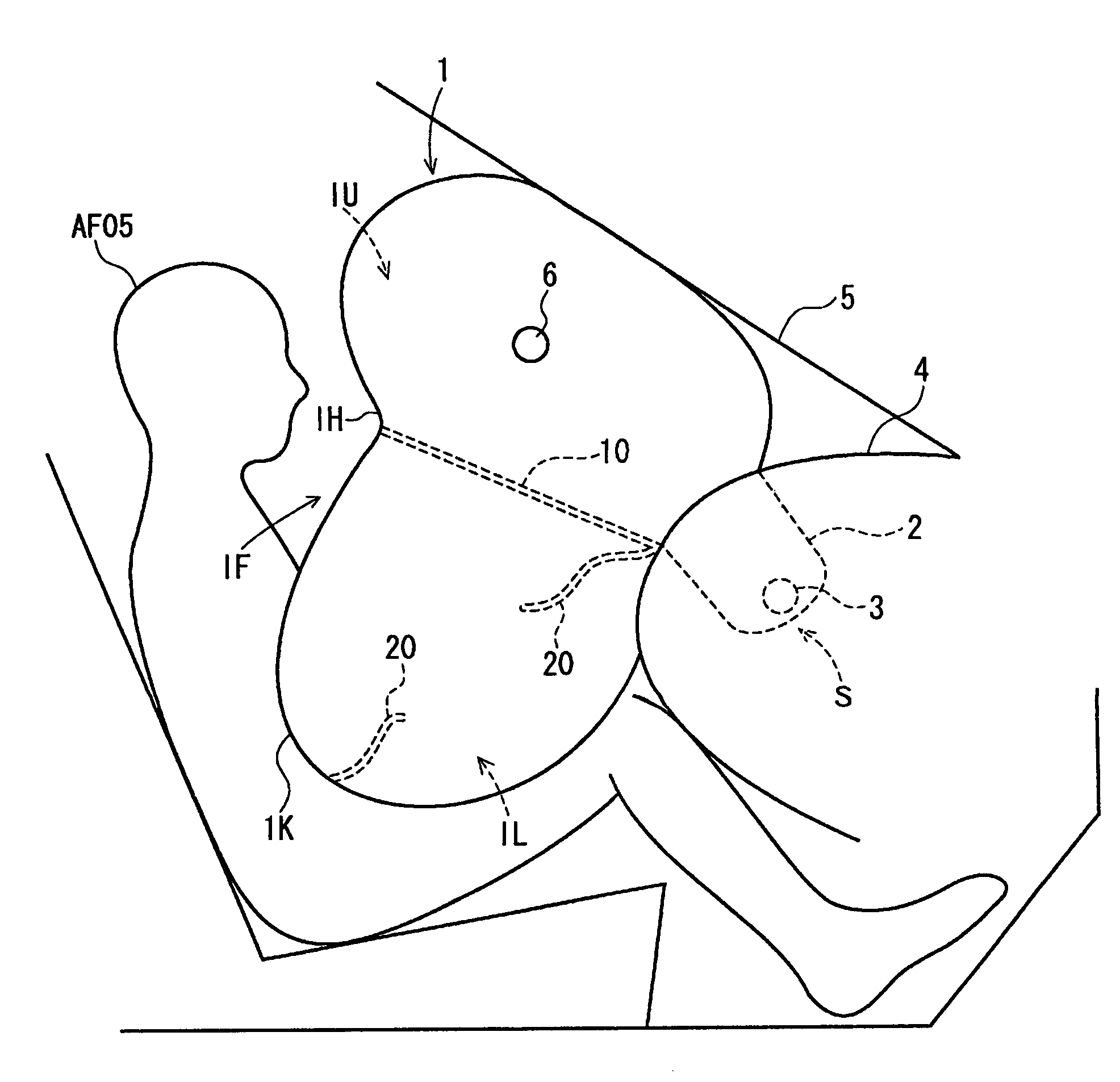
[0034]In the airbag of the present invention (the first aspect) and the airbag device of the present invention (the fourteenth aspect), the regulation member regulates the inflation of the head counter portion of the occupant counter surface of the airbag, which confronts the occupant head upon inflation of the airbag toward the occupant for the period from start of the inflation until an elapse of a predetermined time. In the case where the occupant is seated by sliding the seat forward, and the airbag is brought into contact with the occupant head before the elapse of the predetermined time from the start of the airbag inflation, the regulation member regulates the inflation of the head counter portion toward the occupant. This makes it possible to prevent the strong contact of the airbag with the occupant head. At this moment, the regulation member reduces the capacity of the airbag so that the inner pressure of the airbag is smoothly boosted to sufficiently protect the occupant head.
[0048]According to the eleventh aspect, the opening formed in the sub-regulation member allows the fragile portion to be easily formed in the sub-regulation member. As the opening is spaced apart from the end portion of the sub-restriction member at the side opposite the occupant, the gas blown from the inflator is guided to the sub-regulation member and likely to flow to the lower portion of the airbag, thus inflating the lower portion of the airbag promptly.

Problems solved by technology

In such a case, there may be a risk of strong contact between the occupant head and the occupant counter surface 101F.
The use of the lifting cord to regulate the inflation of the occupant counter surface toward the occupant may cause the risk of insufficient thickness of the inflated airbag in the longitudinal direction of the vehicle body at the upper end side.

Method used


Image

  • Airbag and airbag device
  • Airbag and airbag device
  • Airbag and airbag device

Examples


Embodiment Construction

[0076]The present invention will be further illustrated with examples below referring to the drawings.

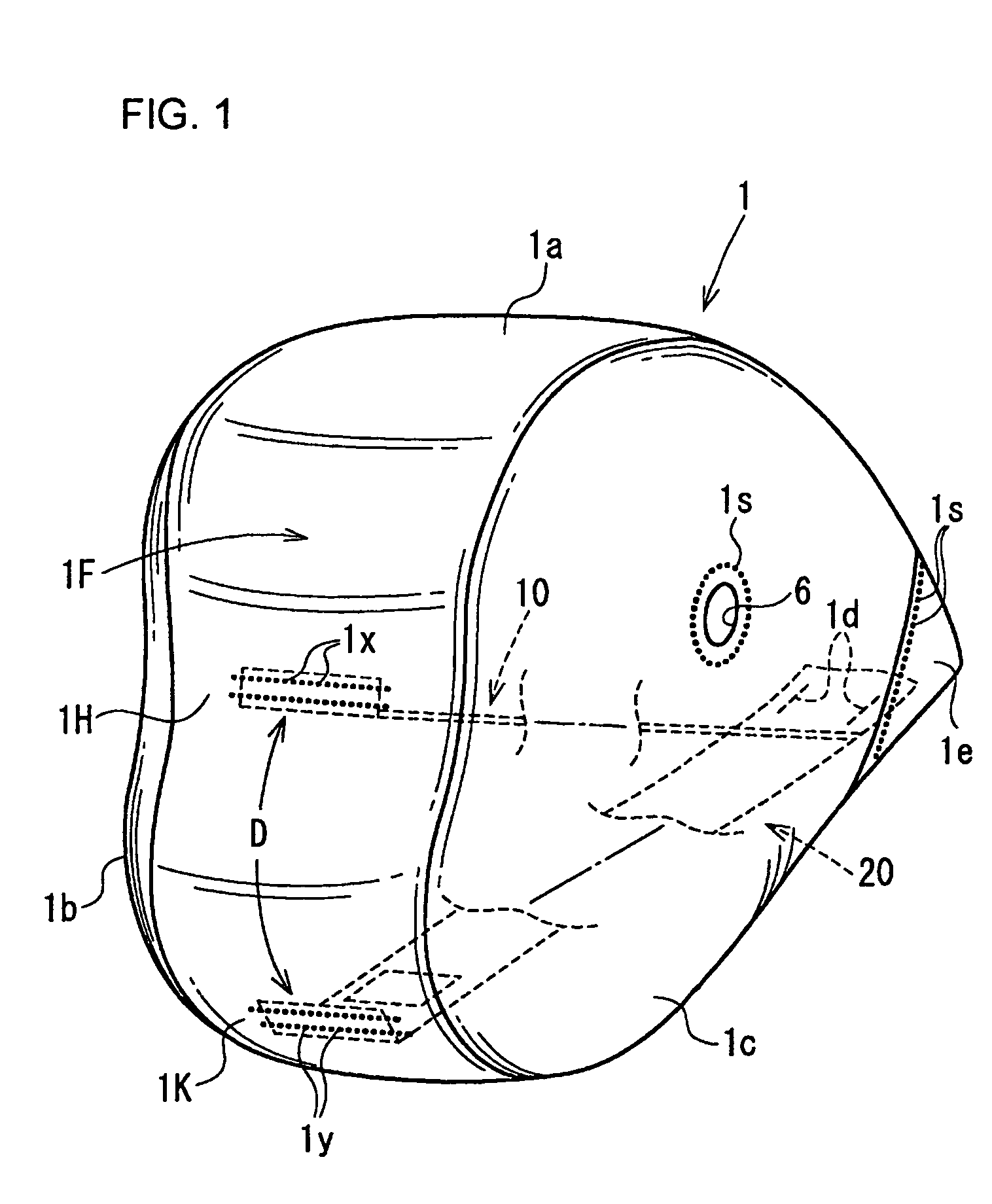
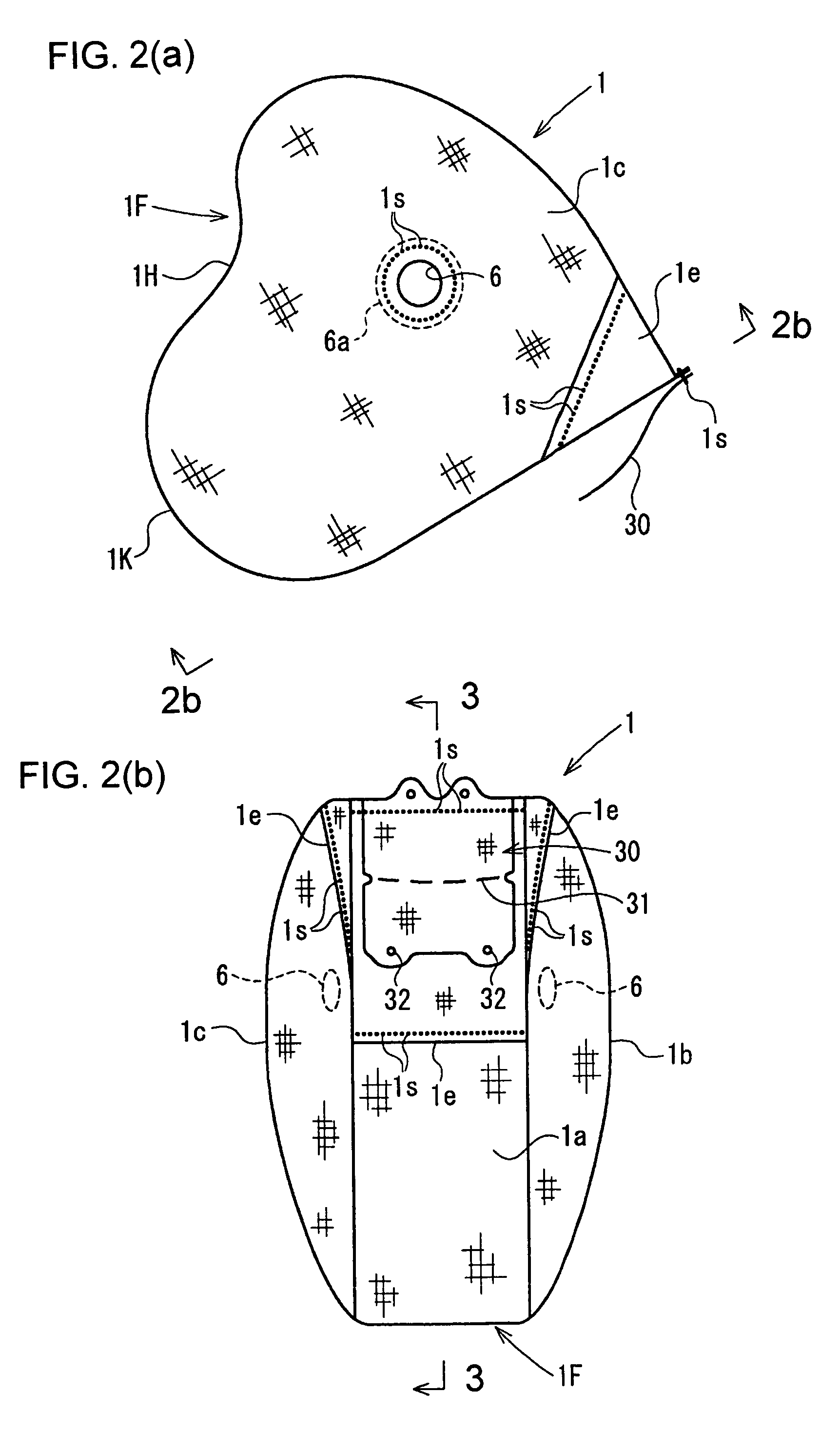
[0077]FIG. 1 is a perspective view of an inflated airbag according to an embodiment of the present invention. FIG. 2(a) is a side view of the inflated airbag. FIG. 2(b) is a view seen from line 2(b)-2(b) of FIG. 2(a). FIG. 3 is a sectional view taken along line 3-3 of FIG. 2(b). FIG. 4(a) is a plan view of an upper regulation member. FIG. 4(b) is an exploded plan view of the upper regulation member. FIG. 5(a) is a plan view of a lower regulation member. FIG. 5(b) is an exploded perspective view of the lower regulation member. FIG. 6 is a plan view of the portion around the opening of the regulation member. FIG. 7 is a plan view of the same portion as illustrated in FIG. 6 upon rupture of the regulation member. FIG. 8 is a plan view showing an arrangement of the regulation member in the airbag. FIGS. 9 to 17 are explanatory views representing how the airbag is folded. FIG. 18 is a se...


PUM


Abstract

An airbag for protecting an occupant includes a panel forming the airbag and having an occupant counter surface with a head counter portion to face a head of the occupant when the airbag is inflated. A recess portion is formed in the head counter portion when the airbag is inflated. The airbag also includes a regulation member for regulating inflation of the head counter portion toward the occupant. The regulation member forms the recess portion by regulating inflation of the head counter portion toward the occupant upon inflation of the airbag. The regulation member is configured to release regulation after a predetermined time from a moment when the airbag starts inflation.

Description

BACKGROUND OF THE INVENTION AND RELATED ART STATEMENT[0001]The present invention relates to an airbag having a recess portion formed in a head counter portion of an occupant counter surface of the airbag from the occupant side, which confronts the occupant head upon inflation of the airbag. Specifically, the present invention relates to an airbag provided with a regulation member for regulating inflation of the head counter portion toward the occupant. Upon inflation of the airbag, the regulation member regulates inflation of the head counter portion toward the occupant to form the recess portion. The present invention further relates to an airbag device provided with the aforementioned airbag.[0002]The present invention especially relates to an airbag and an airbag device adapted to the passenger seat of the vehicle.[0003]In the specification, an AF05 dummy stands for a legally regulated crash test dummy in the U.S. for a small-sized adult female in 5 percentile. An AM50 dummy stan...

Claims


Application Information

Patent Timeline
Patent Type & Authority Patents(United States)
IPC IPC(8): B60R21/16B60R21/23B60R21/2338
CPCB60R21/231B60R21/2338B60R21/201B60R21/237B60R21/239B60R2021/23384
Inventor KUBO, YOSHIYUKITERAMURA, TSUTOMUMARUYAMA, TATSUYAUEDA, MASAFUMI
Owner JOYSON SAFETY SYST JAPAN GK
Why Eureka
Try Eureka