Wheelbarrow cover

a wheelbarrow and cover technology, applied in the field of wheelbarrows, can solve problems such as damage to other types of materials, and achieve the effect of preventing environmental damage to contents

Inactive Publication Date: 2015-04-07
PIPKORN RANDALL E +1
View PDF15 Cites 7 Cited by
  • Summary
  • Abstract
  • Description
  • Claims
  • Application Information

AI Technical Summary

Benefits of technology

[0007]As will hereinafter be described in detail, the present invention discloses a removable cover for use on a conventional wheelbarrow. The cover of the present invention is primarily intended to protect the contents of a wheelbarrow from environmental damage during lunch and coffee breaks and other periods of non-use. In particular, in a relatively dry climate with the contents of the wheelbarrow being a curable product such as mortar, workers cannot leave the wheelbarrow unattended for more than short periods of time without the mortar starting to cure. Other environmental conditions such as rain and wind can damage other types of materials which are oftentimes carried in a wheelbarrow. The cover of the present invention is also intended to provide a convenient work surface at a job site which would otherwise not have such a structure.
[0010]As herein before mentioned, in addition to protecting the contents of the wheelbarrow from environmental damage, the cover of the present invention is also intended to provide a convenient work surface at a job site which would otherwise not have such a structure. The previously described upstanding peripheral lip formed on the cover will prevent articles carried on the top of the cover from sliding off, and the multiple compartments formed by the upstanding walls will segregate various articles from each other.
[0011]Accordingly, it is an object of the present invention to provide a new and useful cover for use on a conventional wheelbarrow to prevent environmental damage to the contents of the wheel barrow and to provide a convenient work surface at a job site which otherwise not have such a structure. The foregoing object of the present invention will be more fully understood from the following description when read in conjunction with the accompanying drawings.

Problems solved by technology

Other environmental conditions such as rain and wind can damage other types of materials which are oftentimes carried in a wheelbarrow.

Method used


Image

  • Wheelbarrow cover
  • Wheelbarrow cover
  • Wheelbarrow cover

Examples


first embodiment

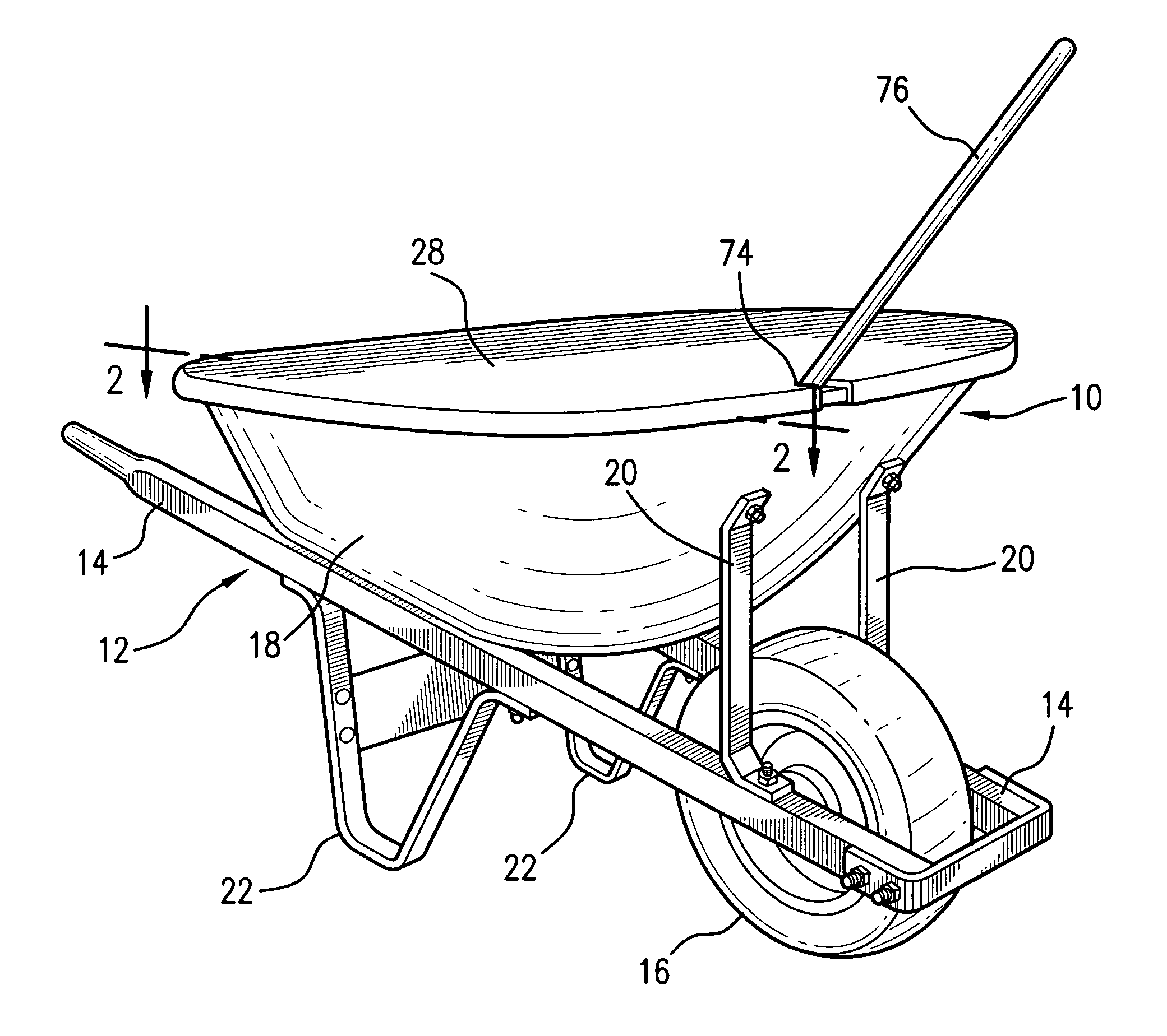
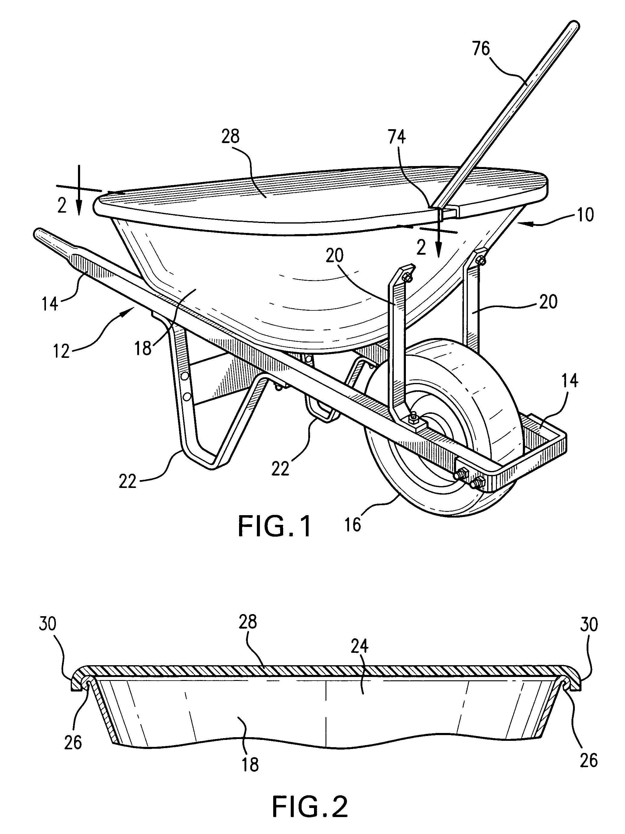
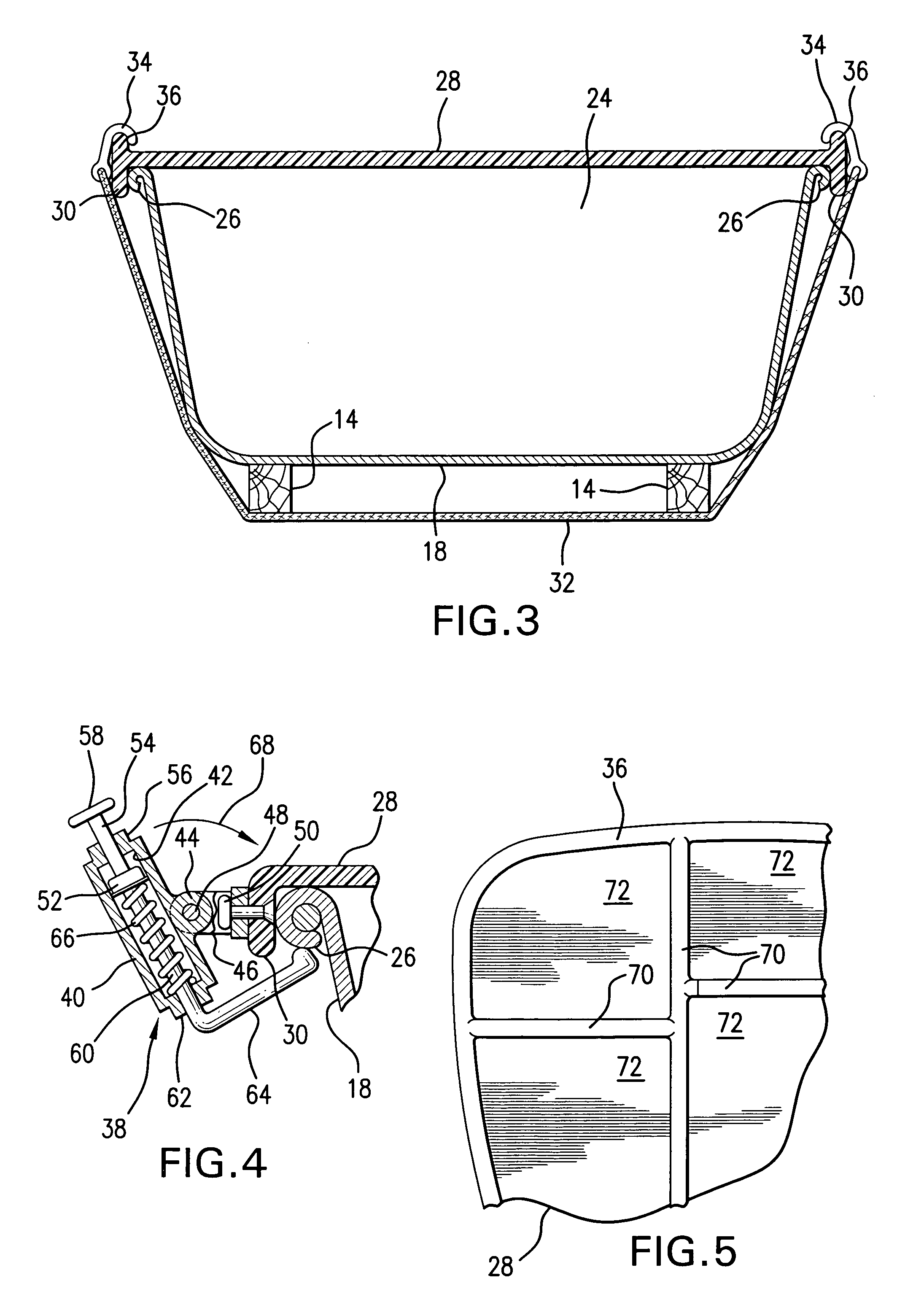
[0021]FIG. 3 shows a bungee cord 32 having a hook 34 on each of its opposite ends. The bungee cord 32 is used to provide a tie-down means for preventing dislodging of the cover 28 such as could occur as a result of severe winds, tipping over of the wheelbarrow or the like. The bungee cord 32 is positioned below the load receptacle 18 of the wheelbarrow 10 with the opposite ends of the cord extending upwardly to position the hooks 34 provided on the opposite ends of the cord in hooked engagement with an endless upstanding lip 36 formed on the periphery of the cover 28. The endless upstanding lip 36 serves a second function, namely it prevents objects (not shown) carried on top of the cover 28 from sliding off the cover.

second embodiment

[0022]FIG. 4 shows a tie-down means in the form of a pair of spring loaded latches 38 (one shown) which are located on opposite sides of the cover 28. It will be understood that the following detailed description of the illustrated latch 38 also applies to the one that is not shown. The latch 38 includes a housing 40 having a bore 42. The housing has a laterally extending ear 44 which is attached to a clevis 46 by means of a pivot pin 48. The clevis 46 is mounted on the depending lip 30 of the cover 28 by means of a suitable rivet 50. A piston 52 is mounted in the bore 42 of the housing 40 and is axially movable therein. A first shaft 54 extends from the top of the piston 52 through a first end 56 of the housing 40 and a pad 58 is provided on the extending end of the shaft 54 by which the piston 52 can be moved manually in the bore 42 of the housing. A second shaft 60 extends oppositely from the piston 52 through the second end 62 of the housing 40 and is bent along its length to fo...


PUM


Abstract

A cover of rigid planar configuration is designed for removable placement on the open top of a wheelbarrow for complete closing thereof to protect materials that are oftentimes contained therein from environmental damage. In particular, curable materials such as cement, mortar and the like will begin to cure if left unattended for more than short periods of time and this problem is particularly troublesome in dry climates. The cover is provided with a depending lip for engaging the sides of the wheelbarrow to prevent the cover from siding movement on the wheelbarrow, and tie-down devices can be used to releasably secure the cover on the wheelbarrow. In addition to protecting the contents of the wheelbarrow, the planar surface of the cover can provide a convenient work surface of use on a job site.

Description

BACKGROUND OF THE INVENTION[0001]1. Field of the Invention[0002]The present invention relates to wheelbarrows and more particularly to a removable cover for a wheelbarrow for preventing the damaging effects of the environment on the cargo carried in the wheelbarrow and for providing a working surface for use at a job site.[0003]2. Description of the Prior Art[0004]Wheelbarrows have been in use for many years and are believed to have appeared in Europe about the eleventh or twelfth centuries. Since that time many improvements have been made to ease the workload on the user and some devices have been devised to perform work on the contents of the wheelbarrow. For example, U.S. Pat. No. 7,070,316 to Roth discloses such a device as having a motor mounted atop a safety shield that is carried on the open top of the load receptacle of the wheelbarrow and the shield partially covers the opening of the receptacle. A drive belt extends from the motor down through the safety shield into the wh...

Claims


Application Information

Patent Timeline
Patent Type & Authority Patents(United States)
IPC IPC(8): A47B23/00B62B1/20B62B5/00
CPCB62B5/0013B62B1/20
Inventor PIPKORN, RANDALL E.PIPKORN, NANCY M.
Owner PIPKORN RANDALL E
Why Eureka
Try Eureka